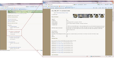
Figure 17: tDAR interface showing a selected 3D object in the Hampson collection
To access the 3D data sets in the Hampson collection housed in the tDAR archive, go to the tDAR home page and search for "Hampson". The Virtual Hampson Museum Project link which will take you to the project page for the Virtual Hampson Project that contains metadata information for the project as well as links to 138 3D data objects within the Hampson collection. Click on any of the 3D objects listed under "Resources within this Project" most of which are identified with a Hampson ID # (Ark_HM_###) and a brief description (Figure 17).
Figure 17: tDAR interface showing a selected 3D object in the Hampson collection
All of the 3D datasets associated with an object within tDAR have been zipped to create a single ZIP file. In addition, the images for each object are available as separate downloads. To download any object, all users must first register with tDAR. Once registered, you will be prompted to enter your username and password during the download process. Because all of the datasets have been compiled together, the resulting file sizes of the zip files can exceed 100mb.
In the following discussion regarding importing a dataset into Rapidform Explorer, the Ark_HM_0011.zip file has been downloaded and all of the contents have been extracted (Figure 18). For each object the original scans are available (with transformation matrices) as well as the registered dataset (point cloud format), the premesh dataset (point cloud format), the mesh dataset and a decimated version of the mesh dataset. In addition, images of the object are also available as well as an Excel spreadsheet that contains the metadata for each dataset.
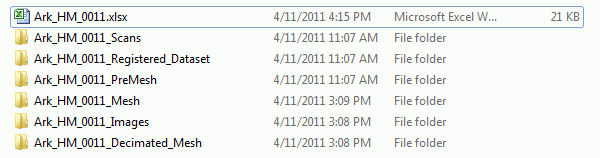
Figure 18: Extracted contents from a zip file for a 3D object downloaded from the tDAR website
There are several free data viewers available for viewing and manipulating 3D point clouds and mesh datasets. For a complete list, please refer to the Data Dissemination section in the ADS Guides to Good Practice for Laser Scanning. From this list, Rapidform Explorer is recommended for viewing datasets from either the Hampson or Amarna archives. This viewer can be quickly downloaded and installed from the Rapidform website.
To open a dataset in Rapidform Explorer, first launch the software and go to File|Open. Next, select the dataset that you wish to open. It is recommended to view the registered dataset or the mesh dataset to view the entire object. Note that only one dataset can be viewed at a time. Upon opening a dataset, the user will be prompted to specify the measurement units for the incoming objects. All objects in the Hampson and Amarna collections are in millimetres (mm).
In the example below, we have opened the mesh dataset for Ark_HM_0011. When a dataset is initially loaded into Rapidform Explorer, the default manipulation mode is set to "selection" which is indicated by the crosshair icon. The selection mode allows the user to select items on the screen such as selecting the object or picking points/vertices for measurement or selecting a reference plane. To toggle between selection and navigation mode, tap the middle mouse button. Note that the crosshair icon indicates selection mode and the chasing arrows icon indicates navigation mode. Once in navigation mode, the user can rotate and view the object from different angles. Tapping the arrow at the top right of the viewing window also toggles the navigation help menu. This menu indicates how to rotate, zoom, and pan a scene. To change the default View Manipulation Style, go to File Preferences. The default mode is set to Rapidform. An alternative viewing mode is the Polyworks view mode. This mode uses each mouse button (left, middle, right) for a 3D viewing function (rotate, pan, zoom respectively) without requiring the use of the Ctrl or Shift buttons and is recommended as the more "user-friendly" mode. Setting the View Manipulation Style is a matter of the user's personal preference, however the navigation help menu is always available by tapping the arrow at the top right of the screen.
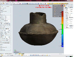
Figure 19: The navigation help menu in Rapidform Explorer
Once a dataset is open, there are several display options that can be adjusted. To turn off the green reference planes located at the object's origin, toggle the eye icon next to Ref. planes under Reference in the Table of Contents on the left side of the screen. Clicking on the Display tab near the bottom left of the screen will change any of the options listed under the Mesh/Point Cloud menu. Of these, toggling the Texture off and on can be useful when viewing a mesh data set as it allows you to better view the underlying surface topography on an object as shown in the figure below.
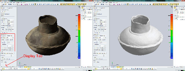
Figure 20: The location of the display tab in Rapidform Explorer which allows the user to change different display options such as toggling object texture on (above left) and off (above right)
Subsampling the static and/or dynamic display ratio can be beneficial on computers that might have limited graphics and/or RAM capabilities. Feel free to explore the different display options that are available.
To adjust the lighting of the scene, go to View|Light Properties. Here the user can adjust the direction and hue of different light sources which can be good for accentuating features on an object n.b. only mesh datasets are affected by scene lighting adjustments. The View|View Clip menu also allows the user to define a clipping plane on an object if desired.
Under the Measure menu, there are several different measurement options available for analyzing an object. The first measurement option, the distance measurement, is the most common. For distance measurements, the user has several alternatives including basic point-to-point measurement as well as vector-to-point, plane-to-point, plane-to-vector, two vectors, and two planes. For a basic point-to-point measurement, choose the "2 Points" option under Method. Next, you can choose to constrain the measurement to a specific axis e.g. constrain a measurement to the Y axis to acquire a vertical measurement for an object. Once you have selected the appropriate method and constraint options, tap the middle mouse button to enter selection mode and then choose two points on the object. A point-to-point distance measurement is computed and is stored under the Measurements entry in the Table of Contents on the left side of the screen. Once the user exits the Measurement menu, all measurements are available in the table of contents.
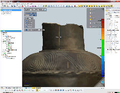
Figure 21: A point-to-point measurement constrained to the Y axis
If you would like measure the distance between planes or vectors, you will first have to fit those primitives to the object. To do so, turn on the Fitting Geometry option then choose either the first (vector) or second (plane) geometry option. Once you have identified enough points on the object to create the desired primitive, the primitive feature will appear in orange. Make sure you hit the blue check "Apply button" next to the "Fitting Geometry" text to confirm the creation of the primitive. Once the desired primitives are created, uncheck the Fitting Geometry option, specify the desired measurement method, and then pick the two primitives onscreen that you wish to measure between and a distance measurement will be computed.
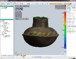
Figure 22: A plane to plane measurement in Rapidform Explorer
There are several other measurement tools available under the Measure menu including angle, radius, section, volume, area, and virtual calipers. The angle, radius, volume, and area options are fairly self-explanatory. The section measurement tool computes a temporary cross section on the object and then allows the user to measure distance features directly on the section (as shown in Figure 23). Unfortunately, only the distance measurement is stored when the section menu is closed.
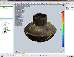
Figure 23: A distance measurement on a cross section
The final measurement tool is the virtual calipers. The virtual calipers are meant to act like a set of physical calipers on a real world object. The different caliper types include outside calipers which can be good for measuring the thickness of an object, inside calipers which can measure the distance between two walls, and depth calipers which can measure the depth of features such as incisings. A detailed video showing the use of the caliper tool is available in this article.
For additional guidance on the tools discussed here, please refer to the Rapidform Explorer help menu. Note that Rapidform Explorer has context-based help so to learn more about a particular tool or menu option, simply tap F1 when the menu menu is open.
The comments facility has now been turned off.
© Internet Archaeology/Author(s)
University of York legal statements | Terms and Conditions
| File last updated: Tue Jun 28 2011