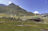
 View the model (requires WebGL compatible browser)
The interface for the rock art and Abri Faravel landscape was created using the Unity game engine. While designing the interface itself posed a number of interesting questions, the process of adapting scan-based data for realtime exploration presented substantial challenges. These were not unexpected and were not unique to this project, but do provide a case study that may be helpful to others presented with similar projects.
View the model (requires WebGL compatible browser)
The attraction of scan-based data is that it is potentially highly accurate and very dense. It is often used as a kind of 'digital cast', documenting sites and objects at high resolution at a moment in time. These are also its weak points. On average present-day computers, the density of scan data still poses challenges for visualising and manipulation – doubly so in realtime applications that must refresh the screen at a rate of at least 15, but ideally 60, times per second. There are also more fundamental problems with scan-based data that divide into issues of geometry and issues of texture. The nature and severity of these problems depends on the scanning equipment and the site or object scanned.
Geometry refers to the 3D surface 'mesh' produced from the cloud of points collected by the scanner. The mesh is composed of a network of triangular polygons (polys (sic)). Unprocessed scan data is simply a cloud of 3D points lacking a surface. In any application where surfaces are required, the point cloud must be converted to a mesh. Simple meshing involves connecting all of the points in the cloud via a network of polys. This remains a computationally heavy task and can consume hours of processing time. The resulting mesh is usually unsatisfactory as the polygon network is too dense for practical display and manipulation. Therefore, a number of processes have been developed for reducing the density of the point cloud and/or mesh while retaining as much fidelity as possible (often referred to as 'decimation'). The variety of techniques for achieving this is too wide to discuss here, but they all result in a lower-resolution, and therefore less accurate representation of the original scan data. The upside is that the resulting meshes are far more computationally efficient and can be visualised and manipulated more quickly. They can also be saved in a number of de facto 3D file format standards for further work in software not specifically designed for processing scan data. Datasets are often decimated by 70% to 90%, leaving a mesh that is only at 30% to 10% of the original resolution. Visually, the difference between a full-resolution and a decimated dataset is often indistinguishable. The more a dataset is decimated, the more quickly it will render to screen and the easier it is to work with, but the less accurate that dataset is. A compromise between speed and accuracy must be made, specific to the requirements of the individual project.
Other geometry problems are usually present in a scan-based mesh. Holes in the mesh are the most common. These are places where the scanner has not been able to record data and so holes are formed. Various forms of interpolation can often bridge or fill these holes, but some are simply too large for filling and must remain in the mesh. Depending on the scanning device and the meshing and decimation processing, the pattern of points and polys in a mesh can be very irregular. This can introduce visual artefacts in lighting and rendering as well as pose difficulties further in the visualisation process when the mesh must be made more efficient, deformed, or when further modelling is required. Related to this are 'reversed normals'. Every 3D polygon has a front face and a back face. This is what determines how the polygon is shaded in response to virtual light. The direction of a face (known as its normal, referring to a ray perpendicular – or 'normal' to the surface) is determined by the order of the points used in its construction. Mesh-generating algorithms sometimes produce meshes in which random polys are 'flipped' or 'reversed' in relation to their neighbours, which produces errors in lighting. These errors are often difficult to track down and fix.
Texture problems relate to the colouring of the mesh surface. This is done in one of two ways, both of which are bound to the geometric properties of the mesh. The simplest and most efficient method is vertex colouring. Each point, or vertex, in a mesh is given a colour value. The colour of each poly is determined by an average of the colours of the three vertices of which it is composed. Many time-of-flight and phase-based scanners produce vertex coloured point clouds. These vertex colours transfer to the meshes generated from the point clouds. When at a sufficient density and viewed at a sufficient distance, the cloud or mesh, appears photorealistic. When viewed too close for its resolution, the cloud or mesh will appear smudged and visual detail is blurred. A more complex, but higher visual-fidelity solution is to drape (map) a bitmap image (texture) over a mesh, tying specific polygons to specific regions of the bitmap. The advantage of this technique is that greater visual detail can be achieved for a lower-poly resolution mesh. Often, the mesh can be viewed much closer while maintaining visual clarity. Mapping a texture accurately over a polygon surface can be very difficult. Sometimes it is impossible, particularly if the texture data is not produced by the scanning device itself. Texture data is frequently not produced by time-of-flight or phase-based scanners, but is often produced by structured light and photogrammetry-based scanners. The higher the pixel resolution of the texture, the more visual detail can be applied to the mesh, the closer the mesh can be viewed without losing focus. There are significant limitations inherent in this method. Average computer graphics processors are limited in terms of the pixel dimension of textures mapped to meshes. The higher the pixel resolution of the texture, the slower it is to render to screen. If a mesh is particularly high-resolution and large (such as a landscape), it may be impossible to texture the mesh at sufficient resolution for 1:1, first-person viewing. Also, the higher the polygon density, the more difficult it is to produce a map for the texture. These maps also increase the file size of the mesh which results in less rendering efficiency. Again, a compromise between speed and accuracy must be found.
Achieving the compromise between speed and accuracy is dependent not only on the geometric and texturing properties of the scan data, but also on the requirements of the project and the limitations of the software and hardware used to process, manipulate and visualise the data. If the data will be processed and visualised entirely within dedicated mesh-processing software, on a dedicated workstation, much higher resolution datasets (perhaps tens of millions of polys) can be used. If the datasets are to be visualised for research and illustrative purposes as still images or animations, 3D modelling software can be used (which usually offer far more sophisticated lighting, animation and rendering options than scan-processing software). But, meshes must usually be reduced in geometric resolution – perhaps only two or three million polys. Geometric resolution of textures must also be considered. Normally a texture no larger than 4096px per side may be used. If the project requires realtime visualisation and manipulation of scan-based data on a wide range of computer hardware, the resolution of the meshes and textures must be greatly reduced. Sometimes a 'polygon budget' of no more than a million polys must be maintained. More often the budget is between 500,000 and 200,000 polys with textures of no greater than 2048px per side.
Two sets of scan-based data are presented in the realtime interface. One dataset covers the rock shelter and its immediate surroundings. It was produced using a Faro phase-based scanner. The second dataset is of the overhanging surface of the rock shelter itself. This was produced using an Artec Eva white-light scanner. The two datasets are at very different resolutions, serving very different purposes. Each presented its own blend of geometric and textural problems. However, these problems are typical in every way of scan-based data.
The data was delivered already heavily decimated in meshes at three resolutions: 4.5 million polys, 3.2 million polys, and 1.3 million polys and vertex coloured. The meshes contained numerous holes (unavoidable given the rocky terrain), and were at a random scale. At a distance, the meshes appeared photorealistic and highly detailed. At first-person, realword perspective, they were very blurry. The lower resolution meshes were particularly unclear. However, the highest resolution mesh was too large to render quickly in realtime. While greater visual resolution could not be added post-decimation, the somewhat better visual clarity of the high-poly mesh could be transferred to a much lower-poly version. Holes in the mesh presented an additional challenge. The mesh was intended for viewing and interaction in first-person but many of the holes were large enough for the virtual person to fall through. These holes had to be closed. Using the open source scan-processing software MeshLab, all of the holes were filled using fairly aggressive interpolation and given white vertex colours. The high-poly mesh was cut into four quarters. Each quarter was mapped for a texture and then the vertex colours were transferred to a 2048px raster-based texture. Each high-poly quarter was decimated to approximately 130,000 polys while retaining its high-poly texture mapping. The result was a much more efficient (in terms of rendering), low-resolution set of meshes which retained all the visual fidelity of the high-poly original and through which the user could not fall. However, even at this resolution, the mesh posed a computational challenge for collision processing. To allow a user to pilot their way across the mesh in first-person, the game engine must calculate the point of contact between the virtual user and the mesh. The higher the polygons, the slower the collision processing. Therefore, a separate collision mesh of only 10,000 polys was decimated from the high-poly mesh. In the game engine this mesh occupies the same space as the higher-resolution mesh, but is invisible, providing only the basis for collision calculations.
The purpose of the interface for the rock shelter scan was to provide the wider landscape context for the rock shelter and neighbouring sites. However, the scan itself covers a limited area in the immediate vicinity of the shelter. Greater landscape context was required. This proved the greatest challenge of the project. The scan data had to be approximately scaled to realworld size by trial and error using known sizes of features within the landscape. Then the data had to be geolocated and correctly orientated. Again, this was very approximate, using rough GPS coordinates and Google Earth. A number of approaches were taken to providing wider landscape context. No high-resolution 3D data was available for the surrounding mountains or valley, so the Google, SRTM-based DEM (digital elevation model) was used. This had the benefit of being texture mapped with aerial photography. However, the height accuracy of these data is very poor – in some places several hundred metres out. This was combined with the low resolution of texture imagery. At first-person perspective the Google data did not present enough visual detail to be useful. An attempt was made to project a panoramic photograph of the site onto the low-resolution DEM. However, because of the low accuracy of the DEM, at this scale, again, the higher resolution imagery could not be sufficiently mapped onto the surface. The final solution was to place the scanned landscape mesh inside an infinitely large cube textured on all six sides with a panoramic photograph taken by the scanner itself. From within the central area of the scan, the two datasets align well enough to provide an acceptable interactive first-person experience. If viewed from the edges of the scan, the alignment between 3D and 2D background is noticeably incorrect.
Although higher resolution, the white-light scan presented far fewer problems. The mesh was provide at 2.5 million polygons and textured with a 1024px (rather small, but proved to be satisfactory) raster, instead of vertex colours. There were no significant holes although there was quite a lot of unneeded and disconnected geometry which was cleaned up manually and using MeshLab's mesh cleaning filters. Because the mesh did not need to align with any wider context, scale and georeferencing were not issues. A 150,000 poly version of the mesh retaining the original texture mapping was produced. A 2,500 poly collision mesh was also created.
This mesh was intended to be viewed both near and far, at any angle, and under different, dynamic lighting conditions. These requirements provide the most significant challenge to realtime visualisation of this mesh. Fortunately, a method for rendering low-poly meshes with very high-poly visual resolution under dynamic lighting conditions is well established in the discipline of 3D graphics for gaming. This is achieved almost entirely through textures, relying particularly on 'normal maps'. A normal map is a colour-coded raster image representing the aspect of a 3D surface. Each pixel is coloured according to the direction in which the polygons under it face. A game engine render reads the normal map to determine shading on a 3D surface. The complexity of a high-poly surface can be 'baked' into a normal map, which is in turn applied to a much lower-poly version of that surface. When viewed in realtime the low-poly surface appears indistinguishable from the high-poly original. This has all of the rendering speed advantages of a low-poly mesh while retaining all of the visual detail of a high-poly mesh. MeshLab provides tools for producing normal maps of high-poly meshes and transferring them to low-poly versions of the mesh. When used together with the original texture image, the version of the mesh in the interface renders quickly while retaining the appearance of the original, dense scan mesh. The very low-poly collision mesh was produced to allow a virtual light source to move across the mesh surface, using collisions in response to user input.
Scan-based 3D datasets are not a panacea for heritage recording and research. They remain difficult to manipulate and visualise, especially in realtime. They possess geometric and textural problems produced by scanning and processing methods that must be resolved. Compromises must be made between dataset accuracy and rendering speed. The Faravel scan datasets provide a case study into how such problems and challenges were met on two different datasets that were intended for different kinds of use. These challenges are common to most applications using scan-based data. It is hoped that others facing these issues will find the processes covered here useful, and that others hoping to commission and use scan-based data in the future will have an insight into how such data can be made useful and will be able to plan accordingly. As computer processing power increases, many of these issues will become less problematic, but they will always need to be dealt with. The solutions presented here are only part of the foundation for creating more elegant and robust ways of visualising and interacting with these rich, but difficult, datasets.
View the model