Cite this as: Swift, E. and Bosworth, L. with Creese, D., Morris, G., Pudsey, A., Richardson, J., Stoner, J., Walker, F and Wright, G. 2021 Creation of Functional Replica Roman and Late Antique Musical Instruments through 3D Scanning and Printing Technology, and their use in research and museum education, Internet Archaeology 56. https://doi.org/10.11141/ia.56.1
The Petrie Museum collection contains c. 60 musical instruments, or parts of them, from the Roman and Late Antique periods. These were mostly either excavated by Petrie and his collaborators in Egypt in the late 19th and early 20th centuries, or acquired there from dealers during the same period. Many are made from organic materials that rarely survive in conditions outside Egypt. These objects have been studied as part of a wider AHRC project on artefacts from Roman and Late Antique Egypt in the Petrie collection, which focuses on the contribution that artefacts can make to our understanding of social behaviour and experience.
In previous research, Swift has drawn attention to the way that the study of functional objects has been neglected in Roman archaeology (Swift 2017, 2–4). Sound-making objects are no exception, and so form a good subject for further investigation. Some of the instruments in the Petrie collection were published with basic descriptions and illustrations by Petrie himself (Petrie 1927) but very few have been included in any subsequent research publications. More widely, surviving examples of ancient everyday musical instruments, both from Egypt and elsewhere, have generally only been published in catalogues, and interpretation has been limited (e.g. Ziegler 1979; Anderson 1976; Sachs 1921). Mostly, researchers have focused on complex, high-status musical instruments such as the lyre and aulos (see for instance Hagel 2013; Hagel 2009, 327–365 and 393–413; West 1992, 49–70, 81–109), and there has been much less attention paid to everyday sound-making objects such as bells and rattles.
A useful approach to functional objects is to consider their affordances – the properties of artefacts that facilitate, and incline people towards, specific uses (Swift 2017, 5–8). Affordances of sound-making objects crucially include their capacity to produce sound of a particular loudness (decibel level) and pitch (frequency) and it was felt that investigating these features of musical instruments in the Petrie collection, by creating replica artefacts, would be useful in evaluating their social uses and significance in society in Roman and Late Antique Egypt. This constitutes the principal aim of the replica creation project. The results of the research relevant to understanding social and cultural life in Roman and Late Antique Egypt are published elsewhere (Swift et al. forthcoming). This article focuses instead on the process of the creation of replica instruments through 3D scanning and printing technology, which can then be used for research purposes, as a methodological case study. It demonstrates the potential of 3D scanning and printing as a research tool as well as its use in museum education. While the use of 3D scanning and 3D printing in archaeology has become more common (see, for example, Barber and Mills 2007; Karasik and Smilansky 2008), as far as artefacts are concerned, 3D scanning is still more commonly used to create replicas for use in public engagement than as a means of conducting innovative research. The article also makes available the .stl files of the replica instruments (Appendix 1) and sound recordings of them (Appendix 2, also available via ADS) which are an important output from the research. Further information about the originals can be accessed by searching for the relevant museum accession number, beginning 'UC..' on the UCL Petrie Collection Online Catalogue.
There is an established history of using artefact replicas in experimental archaeology and the various issues have been widely discussed. Principal problems at the general level include an absence of clear aims, insufficient documentation of processes, compromises in materials or methods that invalidate the results, and lack of academic context (see Outram 2008 for a recent survey). Regarding research aims, Millson recommends 'an objective approach targeting specific questions and resulting in data which can be empirically understood'. Our research aims, as noted above, follow this principle as they are focused on the following questions: 'how loud is the sound of the object?', 'what note/s does the object play?' and 'how audible is the sound at different ranges?'. At a more experimental level, and not counting strictly as experimental archaeology according to the narrower definitions that exist (see Millson 2011, 3; Outram 2008, 4), from the sound recordings, we get a broad impression of how the objects may have sounded within a likely use context. This part of the investigation is more subjective, and of course we cannot replicate the experience of ancient listeners, who would be operating within very different cultural norms and expectations (Betts 2017, 23–25). Yet we judge it still to be a worthwhile process, as the alternative would be to neglect the gathering of information, however partial, concerning the wider auditory experience. We need to be able to consider what contribution sound-producing instruments made to the social environment of the past, and to do that some re-creation of acoustics within spaces is necessary.
It is essential to record the process of replica creation in detail, so that experiments can be replicated by scholars to check the results if necessary (Millson 2011, 3–4), hence this article documenting the 3D scanning process, and creation of the 3D models, 3D prints and craft replicas, and the provision of data for others to use in further replica creation. Concerning compromises in the methods and materials (the third point raised by Outram 2008), if it is not feasible to use completely authentic materials and processes, potential issues arising can best be dealt with by trying to ensure that the materials and production methods used have as little effect as possible on the functional features of the objects that are the subject of the enquiry. We have taken this approach, creating what are sometimes termed 'functional replicas', which aim to replicate accurately only those selected features under investigation rather than aiming for total authenticity in all aspects (Mathieu 2002, 3). The materials and production methods outlined below, and decisions made about various aspects of form where data were otherwise lacking, certainly affect how closely the replica artefact mimics the original sound of the object. The main requirement as to methodology is that the methods used produce objects of the same dimensions as the originals, since the dimensions are the crucial factor in the analysis that affect decibel levels and frequencies. Materials discrepancies are less important, as they will potentially have more of an effect on the timbre than they do on the decibel levels and pitches (frequencies) which are the focus of our investigation. Naturally, some objects have entailed more compromises than others (for instance, the ceramic rattles), and so produce more limited, and potentially less valuable, data. This will be discussed in further detail below.
The study of the replica objects has been integrated into a broader study that takes into account further evidence both from archaeological contexts of analogous objects, and from visual and textual sources (see Swift et al forthcoming). Fortunately, much information is available concerning ancient music more widely, which has been essential in re-creating, for instance, tunes and rhythms likely to have been played by the instruments (Pöhlmann 1970; Pöhlmann and West 2001; West 1992), and evidence concerning likely contexts of use, within the courtyards of domestic houses, for instance.
Considering previous research on the creation of replica instruments from the Roman period, a number of studies exist, which differ in remit from the current study, mostly focusing on different instruments to those studied here and using more conventional methods. A re-creation of a cornu, for example, draws on measurements taken from the original artefacts, and compositional analysis data, and uses authentic materials and methods as far as possible to re-create the sound of the instruments (Pelosi et al. 2016). Another project uses similar methods to re-create a number of bells, including some Roman examples (Drescher 1998). It also records the audibility of the sound at different distances, but this kind of approach is rare. A research project, the European Music Archaeology Project has constructed replicas of musical instruments from the Roman period, such as sistra, and auloi, as well as a range of instruments from other periods and areas of the ancient world (Both 2019; De Angeli et al. 2018).
As regards projects that use 3D scanning, an aulos fragment from Selinunte has been 3D scanned and printed (Bellia 2015). Another project by the Museum of Fine Arts, Boston, also currently in progress, is focusing on auloi fragments, see Conservation Project: Auloi of Meroë. The closest study in terms of methods and type of instrument studied is a research project that investigates the possible notes produced by a set of panpipes from, probably, Tebtynis, or perhaps Saqqara (Avanzini et al. 2015). The panpipes were 3D scanned using a similar methodology to that outlined below; however, the pipes were not printed but instead the sounds produced by individual tubes were evaluated by studying the 3D data and modelling the sounds that would have been produced. This is a useful comparative study to our investigation of the Petrie panpipes, below, illustrating how different decisions can be made concerning reconstruction processes based on 3D scan data.
Twenty objects from the Petrie Museum were selected for replica creation. The selection was chosen to be broadly representative of the existing object types and materials, focusing on those objects in a good state of preservation that were suitable for scanning (although still inevitably including a few artefacts that were incomplete or with minor damage). The use of a high-quality scanner, the Romer Absolute Arm, made possible the scanning of metal artefacts with reflective surfaces that otherwise present challenges to 3D scanners. The artefacts are listed in Tables 1, 2 and 4, with descriptions and further information obtained from personal examination of the originals, and comprise bells, cymbals, rattles, clappers, a set of panpipes and a set of double pipes. As far as can be determined, other than the wind instruments, none of these categories of instruments have been replicated using 3D scanning technology to date. Further details regarding dating and parallels for the artefacts may be found elsewhere (Swift et al. forthcoming). It is sufficient to note here that most can be dated stylistically to the Roman or Late Antique period, from comparisons to extant artefacts found in secure archaeological contexts, although two artefacts proved on investigation to be of likely Islamic date (UC59260 double pipes, and UC30389 rumbler bell). They are included here for completeness, and because the replica information will be of use to those studying the Islamic period.
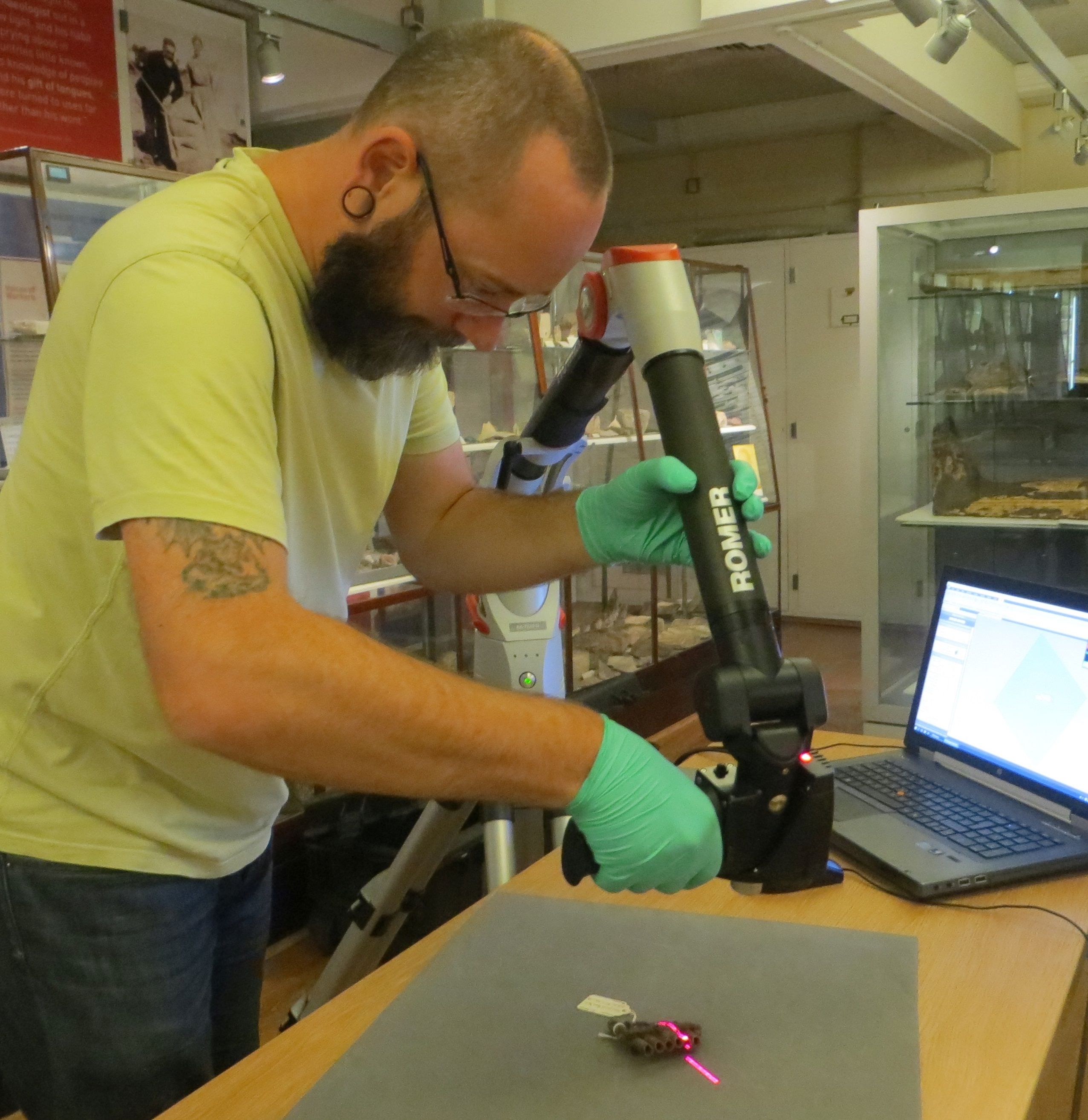
The equipment used in this project was the Romer Absolute Arm 7320 SI, a portable laser scanner capable of fast, accurate and reliable 3D point cloud acquisition. The Romer's integrated RS4 scanning head can produce surface measurements to an accuracy of 0.046mm. With its ease of use, great range of movement and its portability, the Romer has the flexibility to perform in many situations without the need for a turntable or specialist lighting equipment typically required for other methods such as photogrammetry. Figure 1 shows the equipment in use at the Petrie Museum.
The Romer is not without its limitations. Firstly, at £50k (2012 prices), it is unlikely to be a cost-effective solution for most seeking to create 3D models for analysis or research. Indeed, with such a high 'buy-in' price, photogrammetry becomes a more realistic and relatively cheap alternative that can produce remarkable results for very little initial financial outlay. Even so, with accuracy and resolution increasing with camera quality, the best results with photogrammetry can only be realised with the highest quality camera equipment, with a correspondent increase in cost.
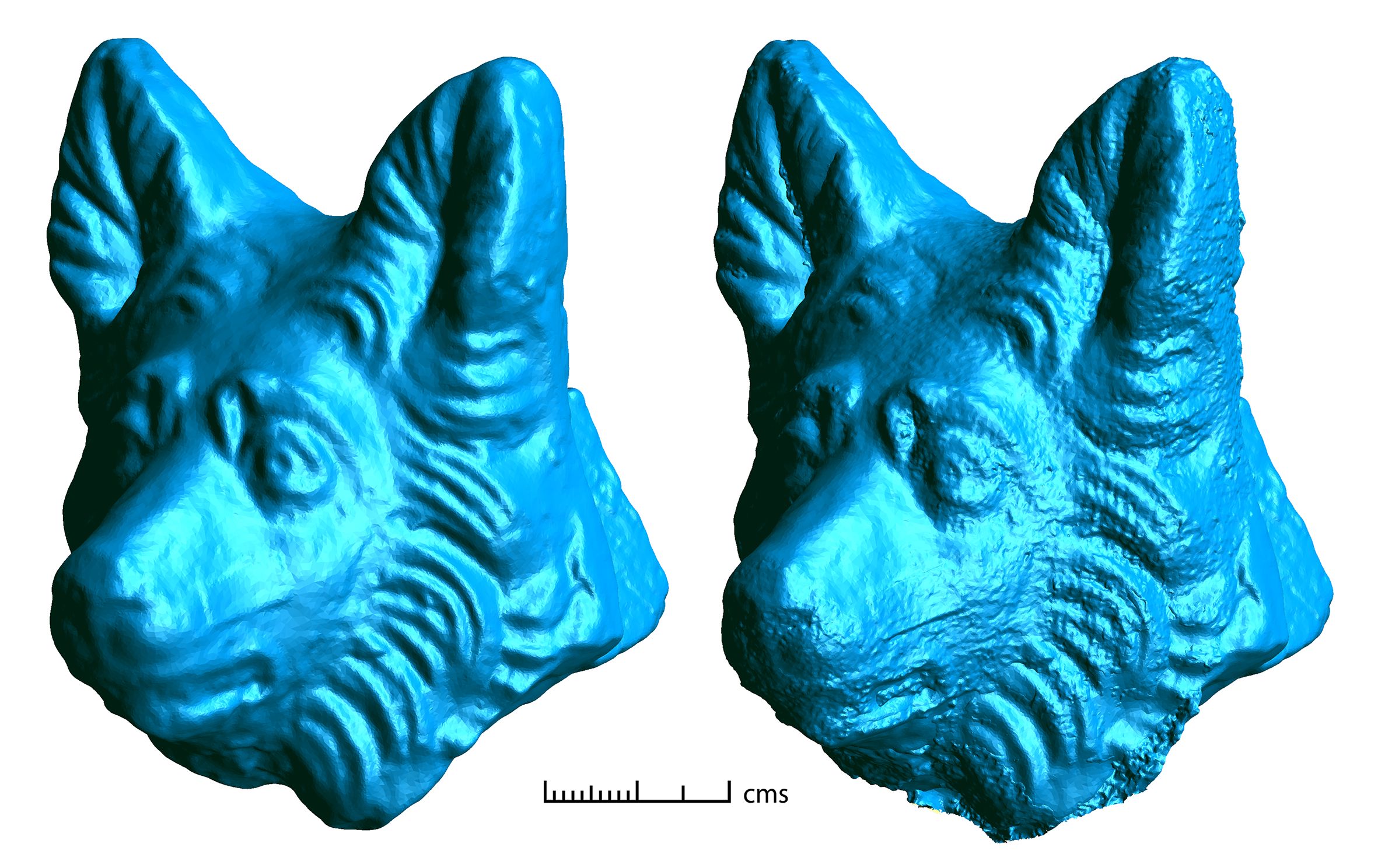
Our experience of photogrammetry using Agisoft's Metashape (formally called PhotoScan) is that while high-quality modelling is possible, we have yet to reliably reproduce results of a consistently high quality with our current photographic setup. Our findings are that with photogrammetry we can achieve similar levels of dimensional accuracy to laser scanning, but the overall reproduction of detail is below that obtained from laser scanning (Figure 2). Additionally, the acquired laser scan data is captured at 1:1 scale, meaning measurements equal to the precision of the original scan data can be taken without the need for calculations based on control points as is the case with photogrammetry. These experiences, balanced against the tried and tested technology of laser scanning with its robust history of producing consistently accurate results (e.g. in Swift 2014), have informed our decision to choose laser scanning over photogrammetry.
Unlike photogrammetry, laser scan data produced by the Romer does not contain colour information. It is possible to 'texture map' an object during post-processing using colour photographs, but this technique suffers the same issues as photogrammetry, where the colour information can appear stretched and distorted as the software attempts to conform a two-dimensional image to a three-dimensional surface.
It is also important to note that, for accurate data recording, the Romer laser scanner is reliant on its own stability and that of the object being scanned. With point spacing at 0.046mm, movements of under a millimetre will create noticeable errors in the data. Of course, the operator should not rely on visual inspection of the data and rescanning problematic areas alone. Steps must always be taken to mitigate such unwanted movement in the first instance and, while solidly constructed tables and concrete floors would be the gold standard, they are not always available.
The scanning works by using a laser beam to capture the position of points on the object in relation to a known reference point. The resulting point clouds are then used to build a highly accurate polygon model with an error range of ±0.14mm at the data capture stage.
The workflow described here uses three commercially available software applications. The principal workhorse of the workflow is Geomagic Studio (henceforth Studio), a computer-aided design software package used for controlling the scanner and processing the 3D model data. Studio uses a proprietary file format (.wrp) which is used during processing for convenience. Models can be exported to a variety of file formats, including the common .stl, .ply and .obj. Studio allows for the capture of data as unordered point clouds, ordered point clouds, or both of these simultaneously. Unordered point clouds are the raw data as recorded by the scanner and will include all stray and erroneous points as well as any points that fall outside the machine's margin of error. Dependent on the speed at which the laser is passed over the object, these point clouds will typically contain varying levels of point density. Ordered point clouds are scan data that have been pre-processed by Studio to remove the majority of scanning errors, creating a cleaner model. Ordered point clouds are also transformed into an ordered grid, evening out the point density across the whole model. Typically, ordered point clouds generated in this way correspond well with the original object; however, as this process cannot be reversed, scan data is recorded in both ordered and unordered format to preserve any detail that could be lost during transformation.
The two other software applications used are Autodesk Maya (henceforth Maya) and Autodesk Mudbox (henceforth Mudbox). Both Maya and Mudbox are used extensively in the film and entertainment industries for creating 3D digital assets. Maya uses metrical input to define the dimensions of shape primitives (cube, triangle, torus, etc.) that when combined together form a 3D digital asset. Mudbox has a more sculptural workflow, utilising tools such as smooth, sharpen, smudge and fill to create more organically shaped assets. Both Maya and Mudbox are used to repair incomplete models by re-creating the missing parts that are then combined with the original scan data.
With laser scanners being capable of quickly producing very large amounts of digital data, consideration must be given to how these data will be stored. The finished digital products at the end of this project may only be a few hundred megabytes in size; the total size of the dataset, including photographs and incremental files, is 6.33GB.
There are three stages to the scanning workflow: inspection, scanning and post-processing. The final post-processing stage may also involve reconstruction work, particularly if the object is incomplete and the output is desired to show an 'original' appearance.
The visual inspection stage identifies potentially problematic areas of the object and offers the chance for the scanner operator to familiarise themselves with the object and its three-dimensional form. A plan of action can be formulated that aims to simplify the scan process to minimise not only the time spent scanning and post-processing, but also to reduce the handling of the object to a minimum. Surfaces not conducive to laser scanning, i.e., reflective, polished, transparent or partially opaque materials, can also be identified. The Romer scanner is capable of recording many of these traditionally difficult surfaces by varying the laser beam intensity through an automatic calibration process. It is unusual for an object to be scanned fully in one pass and invariably the object will require turning/rotating for further scan passes to be made that ensure complete coverage of the object. Repositioning an object with loose, removable, or moving parts will inevitably cause misalignment issues during the scan alignment phase of post-processing. If removable or moving parts cannot be secured for the duration of the scan, then, if possible, separate scans of these parts should be made to be digitally 're-attached' to the model during post-processing. There is little that can be done with loose parts that move when the object is handled, other than to handle them as carefully as possible to minimise potential misalignment during post-processing.
The scanning of an object should take into account any issues identified during the inspection phase and be approached in a methodical manner. Poorly scanned areas are usually easy to identify during scanning and can be re-scanned 'on-the-fly', but areas that have been missed completely are more difficult to identify without undertaking some preliminary scan alignment immediately after capture. Alignment tolerances can be relaxed here as the purpose is to quickly assess the completeness of the scan data, rather than to create a finished three-dimensional model. It may not be possible to scan an object in its entirety and problematic areas other than those previously identified during the visual inspection may surface as the scan progresses.
Post-processing the scan data to create a finished model can begin once all the scan data for the object has been collected. As much of the post-processing work is destructive, that is, causing non-reversible deletions or alterations to the underlying scan data, working copies of the scan files are created to ensure that the original scan data is always available in case of data loss. Initial processing involves deleting any points that are not part of the object, e.g. any supports used to secure the object in place, or the tabletop/surface upon which the object was placed. Automated processes, such as removing disconnected points, are all carried out at this stage. To retain data integrity, at no point are automatic smoothing and noise reduction processes applied to the whole model. However, it may be necessary to reduce noise, particularly where the surface has not scanned well (e.g. reflective or transparent surfaces), but this is carried out in localised areas and only when deemed absolutely necessary.
Each individual scan pass creates separate point clouds that are organised into scan groups within Studio. Before further processing can be undertaken, these individual scan groups must be combined to form one, larger, single point cloud. During this process, areas with overlapping points are analysed for points that lie outside the statistical average, with these points being automatically deleted, removing any overlapping scan passes and reducing and optimising the scan data for further processing.
Once the point cloud is cleaned and optimised, it must then be converted to a polygon mesh. Converting to a mesh will often highlight further errors in the point cloud, such as non-manifold edges, self-intersections, highly creased edges, etc. These must be removed before further work can be done. At this point there are usually areas of the model with missing data that are visible as holes. Small holes can be filled without too much trouble, but larger holes may need extensive reconstruction work to fill. The amount of work needed at this stage can be reduced by careful planning and a thorough approach to the collection of data from the beginning.
At this stage there will usually be multiple polygon models and at the very least this will be two opposite sides of a whole object. These will need joining together to form one whole model, which is a simple automated process whereby shared points between model pairs are selected and a best fit is achieved using statistical averaging. This process is repeated for each polygon model, gradually building up to the completed object.
This is perhaps the earliest stage at which a 3D model can be considered finished, when a complete model, with all holes filled and scan errors removed, has been created. However, further work may be undertaken, such as adding colour to the model by the process of texture mapping high-resolution photographs to the surface (not carried out for this project), or by reconstructing missing or damaged areas. For simple shapes this is a relatively easy, though sometimes time-consuming, process, but more complex shapes may take many hours to complete.
Other than the clappers, which were very straightforward to produce using the above process and so will not be commented on further, each object that was scanned for this project presented unique problems that needed to be solved. The following short case studies taken from the project illustrate real-world examples of problem solving when working to re-create historical objects through 3D scanning and modelling.
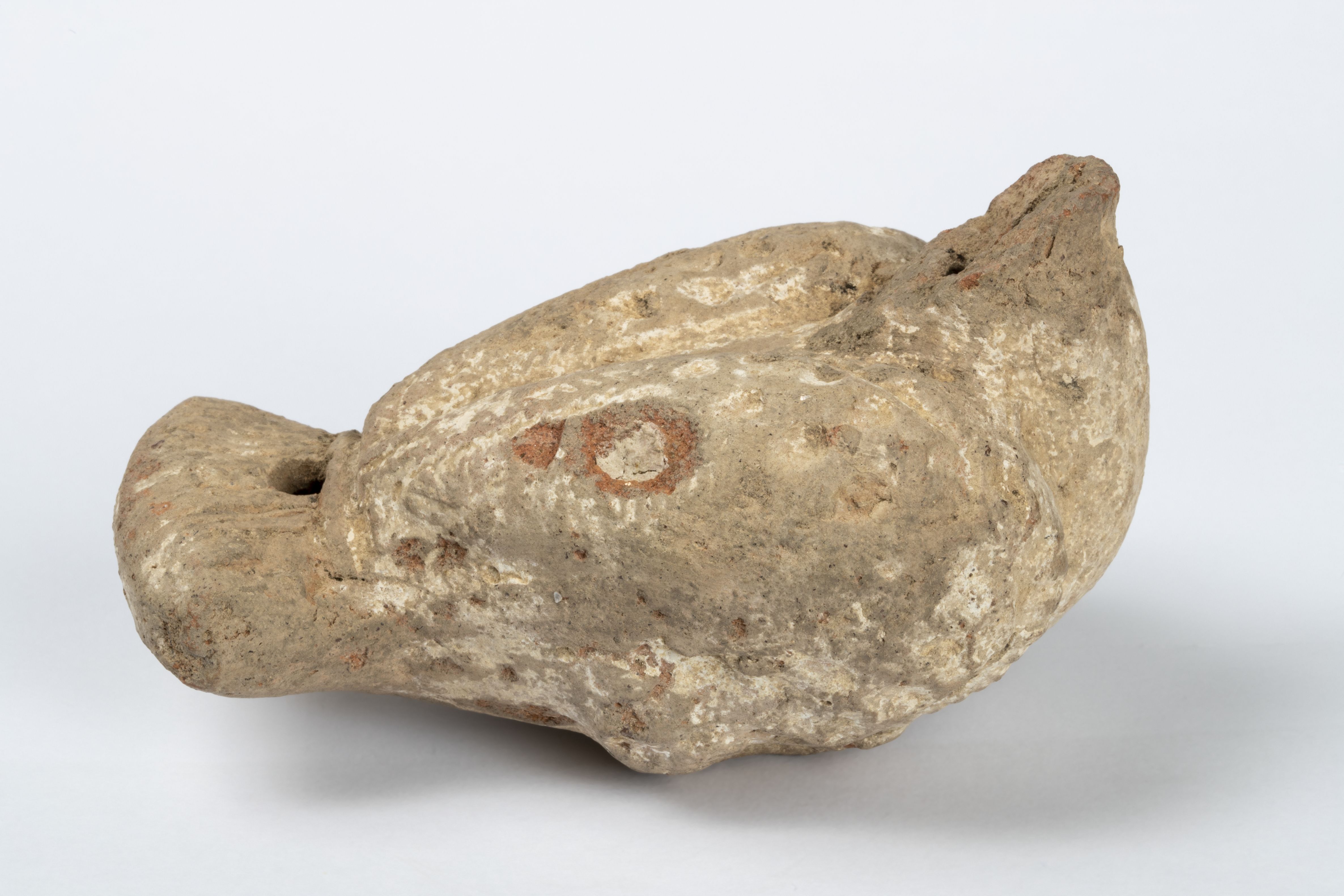
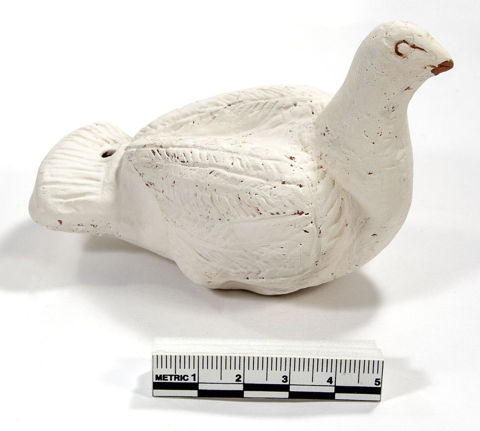
The bird rattle had suffered considerable damage and was missing the head (Figure 3a). The decision to use a low polygon head as part of the reconstruction was taken as there were no direct references for this particular object from which to work (i.e. no close parallels known from the archaeological record). It is, however, possible to create a very detailed reproduction of a missing part based on similar objects, if they are available. After initial cleaning and repairing the scan data within Studio, the model was exported in .stl format and imported into Autodesk Maya, where a low polygon head was created of roughly the correct proportions. This was then exported again, this time as an .obj file, to be imported into Mudbox. Now within Mudbox, the low polygon head could be sculpted and blended into the body of the bird, creating a seamless composite and a fully reconstructed object.
Opinion was sought from a pottery specialist on the manufacturing process of the bird. While there were few easily identifiable production marks on the object itself, it was determined that the most likely technique would be that of two half-moulds joined together before firing as a whole. The scanning process, however, produces a solid object, so to re-create the bird as a functioning instrument, it would need hollowing out. The bird has two original holes, plus a third in the neck exposed as a result of the missing head. Studio has no specific tools for creating a hollow object, but a wall thickness can be applied to the model that effectively creates a hollow object. This was not essential for the production of the ceramic replica (see below; illustrated in Figure 3b), as it could be created at a later stage; however, experimenting with the tools available, a process of trial and error resulted in a realistic wall thickness based on the details that were obtained from measurements of the object. A CT scan might also be used to verify the wall thickness of objects, at a cost of approximately £200 per object without additional handling or transport costs, but was not costed into the funding application and so could not be used on this occasion.
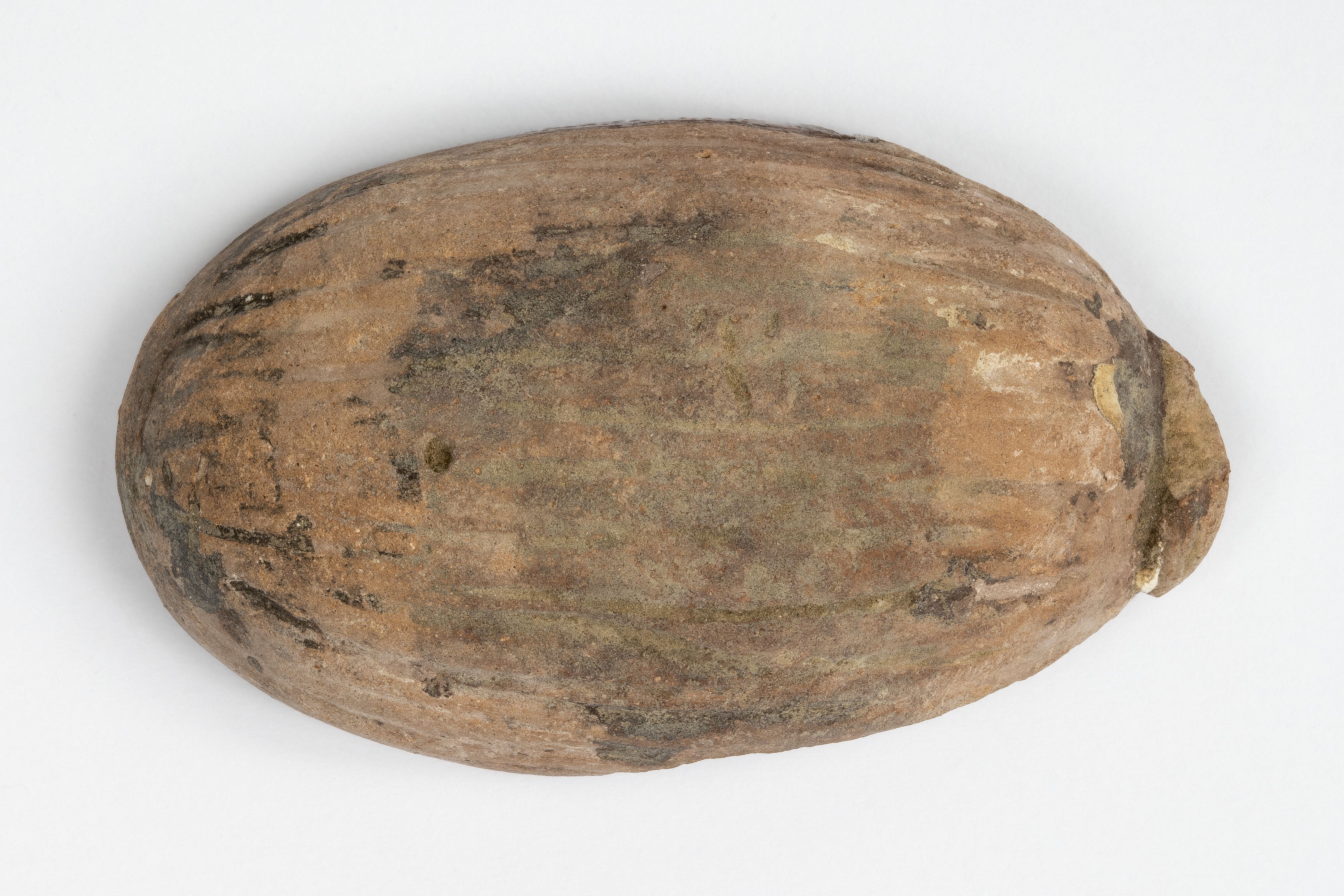
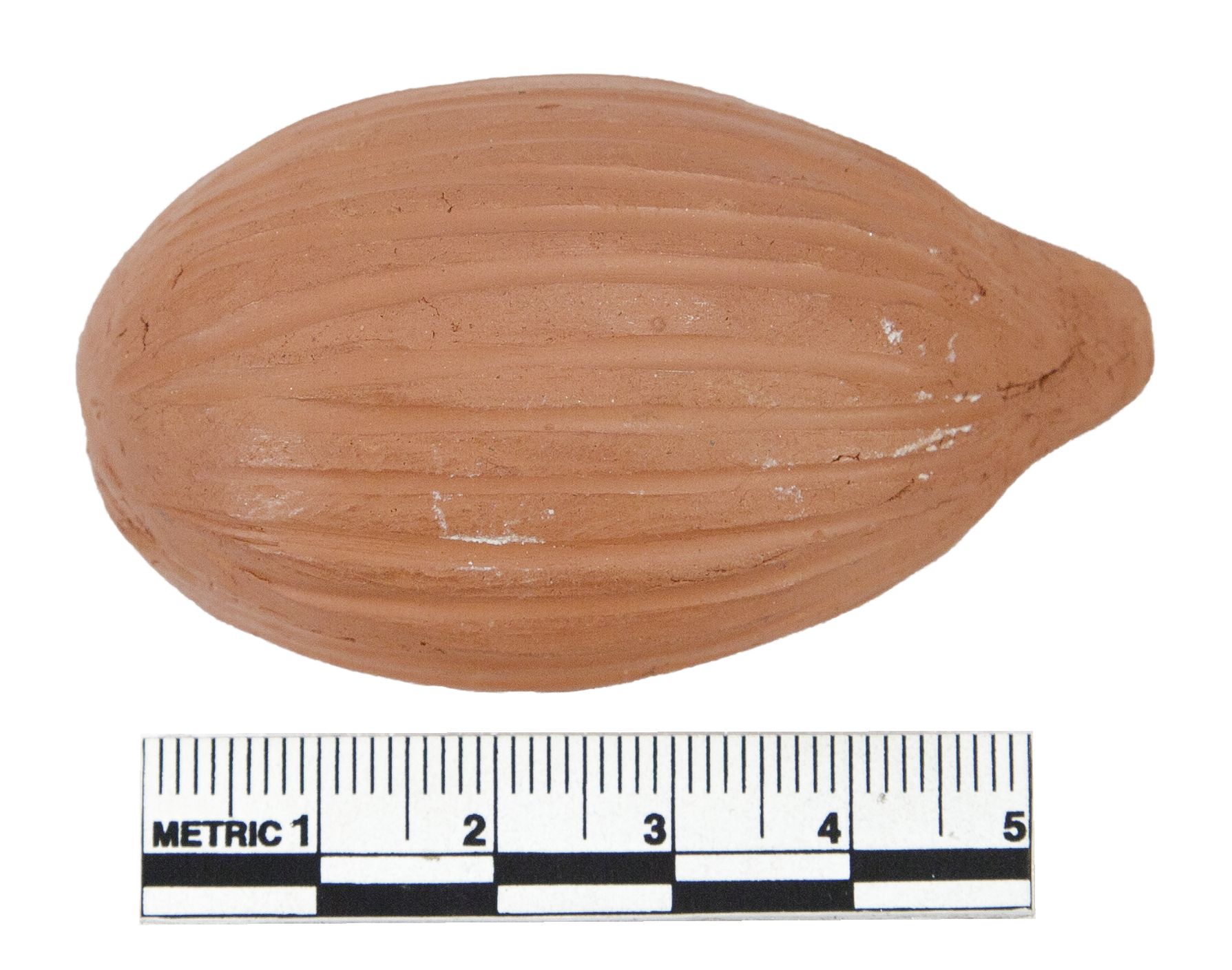
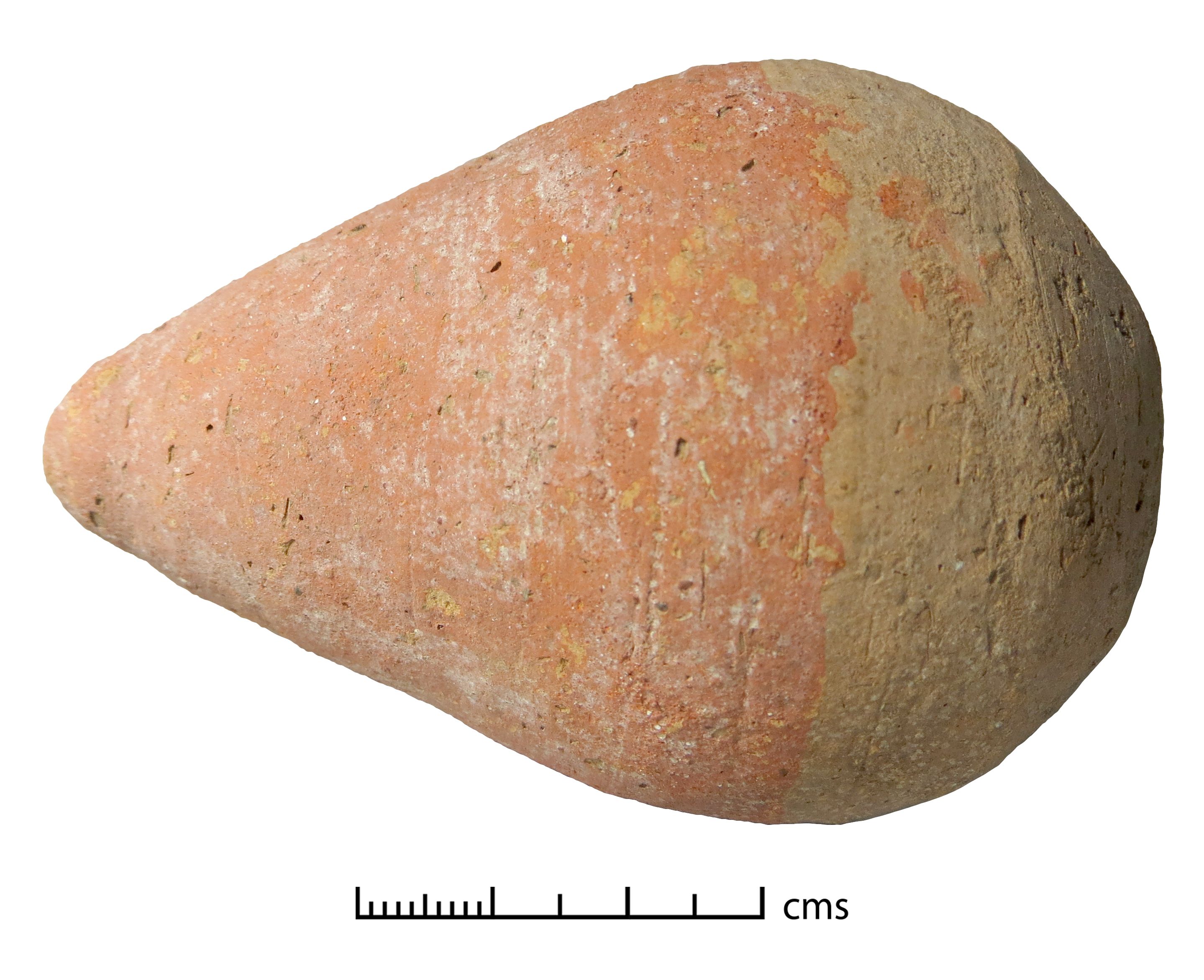
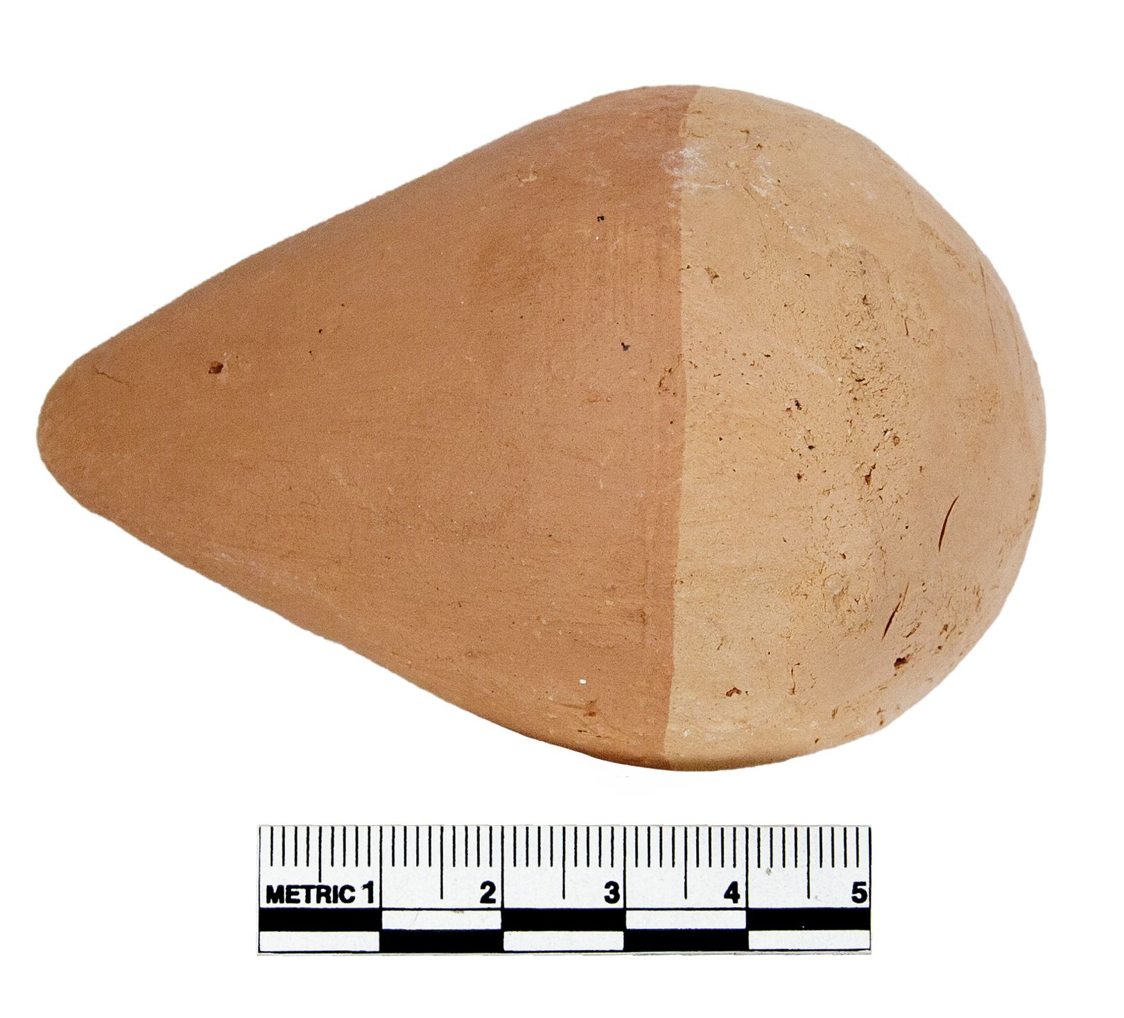
The nut-shaped rattle was incomplete, and appeared to have split down an original seam between the two halves (Figure 4a shows the original and Figure 4b the eventual replica). This allowed information on the wall thickness of the object to be recorded, which proved to be approximately 3mm thick. The pointed rattle was intact and in good condition (Figure 5a). The modelling of the scan data produced a solid object that was used as the basis for a ceramic mould (see further discussion below; the replica is shown in Figure 5b). For each of the rattles, the size of the 3D model was increased by 9.4% to compensate for the shrinkage rate of the selected clay body (see below).
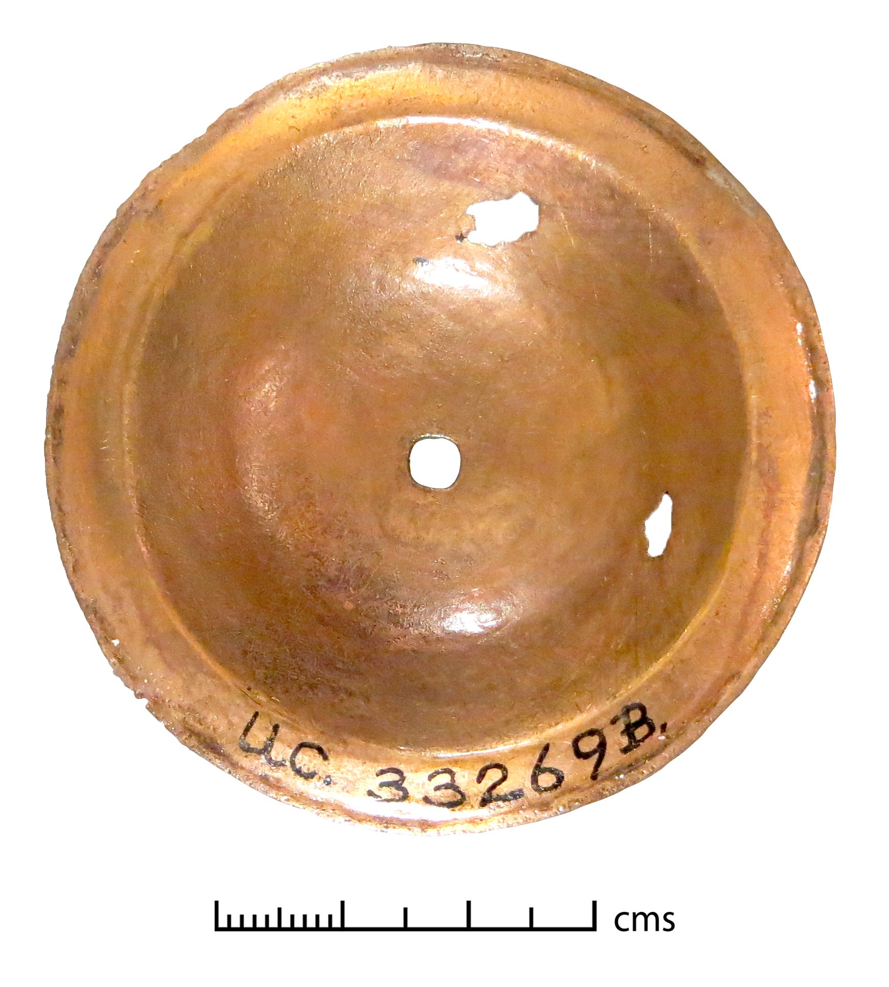
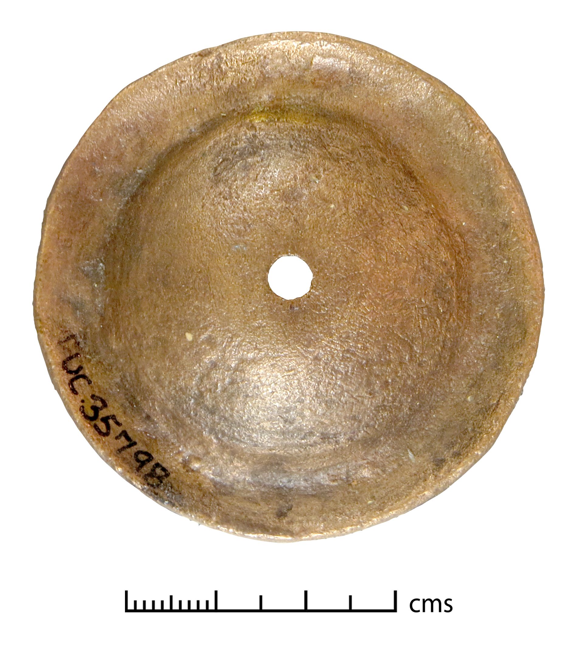
In some ways the cymbals are simple objects to scan, as they are easy to lay flat, have only two sides and have no moving or loose parts (Figure 6). However, their seeming simplicity disguises how a good understanding of later elements in the workflow inform the methodology in earlier stages. Accurate scan alignment relies on obtaining overlapping scan data (i.e. present in separate scans). Since the cymbals were flat and with a thin profile, they posed a particular challenge in this regard. Once the two sides of each cymbal had been scanned, the cymbal was positioned on its edge, supported on either side, so that a third scan could be made that incorporated both sides. The other two scans were then aligned to this third scan. Capturing the thin edge of the cymbal in any useful detail was difficult and, after several attempts, the decision was made not to scan the edges, but to re-create them during post-processing using a hole-filling tool, with further refinements being carried out in Mudbox. Following 3D printing and the initial casting process (see below), the casting failed for the replica of UC35798 (the edges of the object cast successfully, but there was a large hole across most of the front surface). The failure occurred because the cymbal wall was too thin in the front surface area for a continuous metal surface to be successfully formed in the casting. The original object did not appear worn on visual inspection, except perhaps slightly around the central hole. Comparing the area that failed, however, to more noticeable use-wear on other cymbals, it is likely that use-wear to the front surface of UC35798 had caused thinning of the surface. In UC33268B, for example, abrasion (presumably against a metal handle) had resulted in extreme thinning to the front surface similar to the voided area on the failed casting.
We can therefore suggest that the original object would probably have been thicker when it was made, although it would be useful to repeat the casting process using the original dimensions, perhaps with a different alloy, to test further whether a successful casting could be achieved. The model for UC35798 was thickened to a minimum of 0.8mm in the thinnest areas so that it could be cast successfully.
Several bells had moving parts in the form of surviving clappers or split-ring loops, all of which placed limitations on what could be expected from the laser scanner when recording data. As the clappers and split-rings were very small thin objects, it was not practical to scan them. They were omitted from the final models and made individually from measurements and reference photographs during the craft reconstruction stage (see below). The initial casting of UC30389 failed as the bell wall was too thin. Again, this is likely to have occurred through use-wear, and the original wall of the bell would have been thicker when it was made. The wall thickness was therefore increased on the inside to a minimum of 1.2mm in order to achieve a successful casting. Three of the bells were very small, with thin walls and fine incised decoration (UC58536, UC58538, and UC58540). It was felt that using the original dimensions might cause the initial castings to fail here too, and so the walls of these objects were thickened by approximately 0.5mm prior to the casting stage.
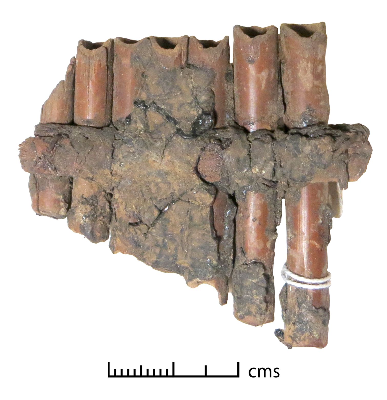
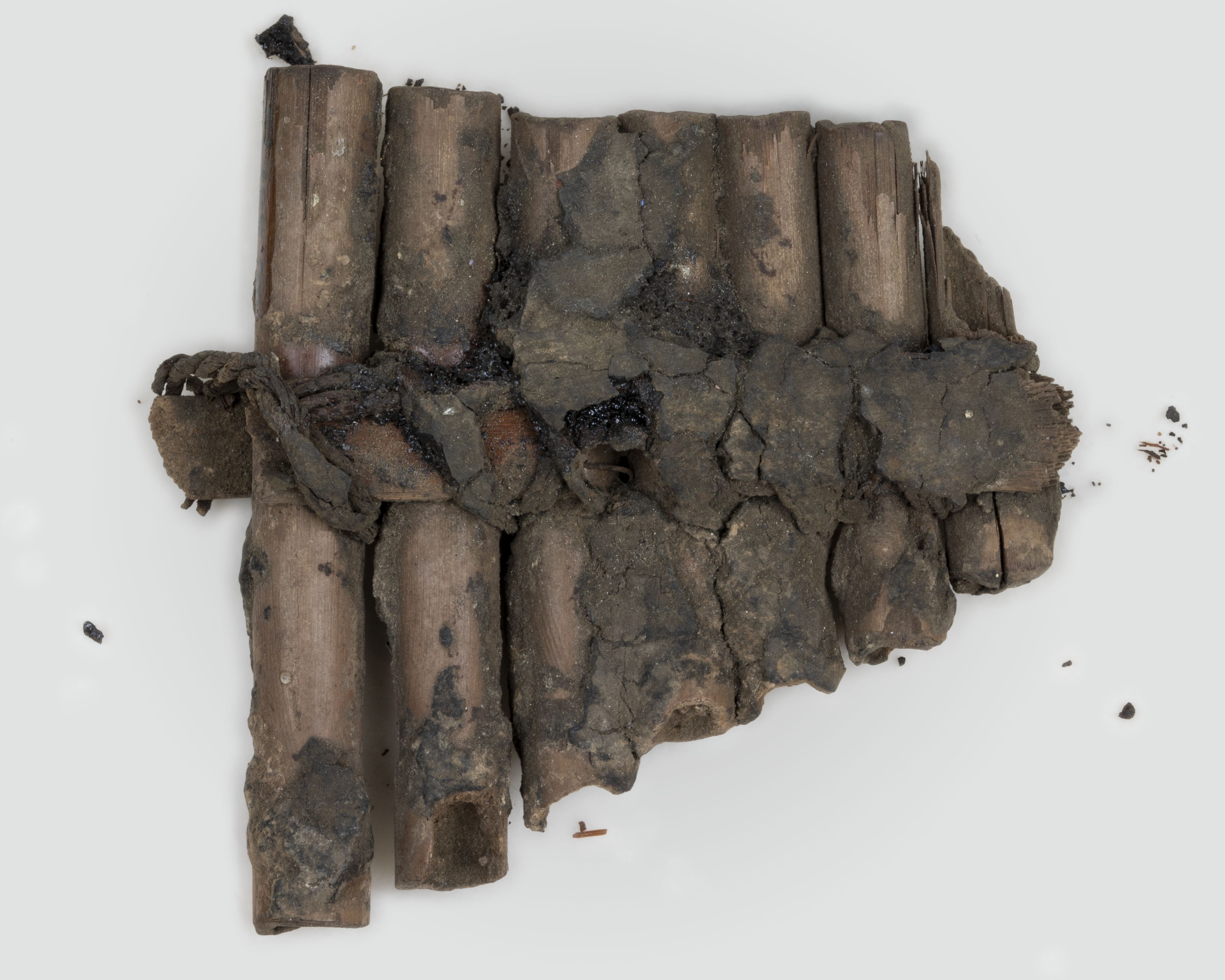
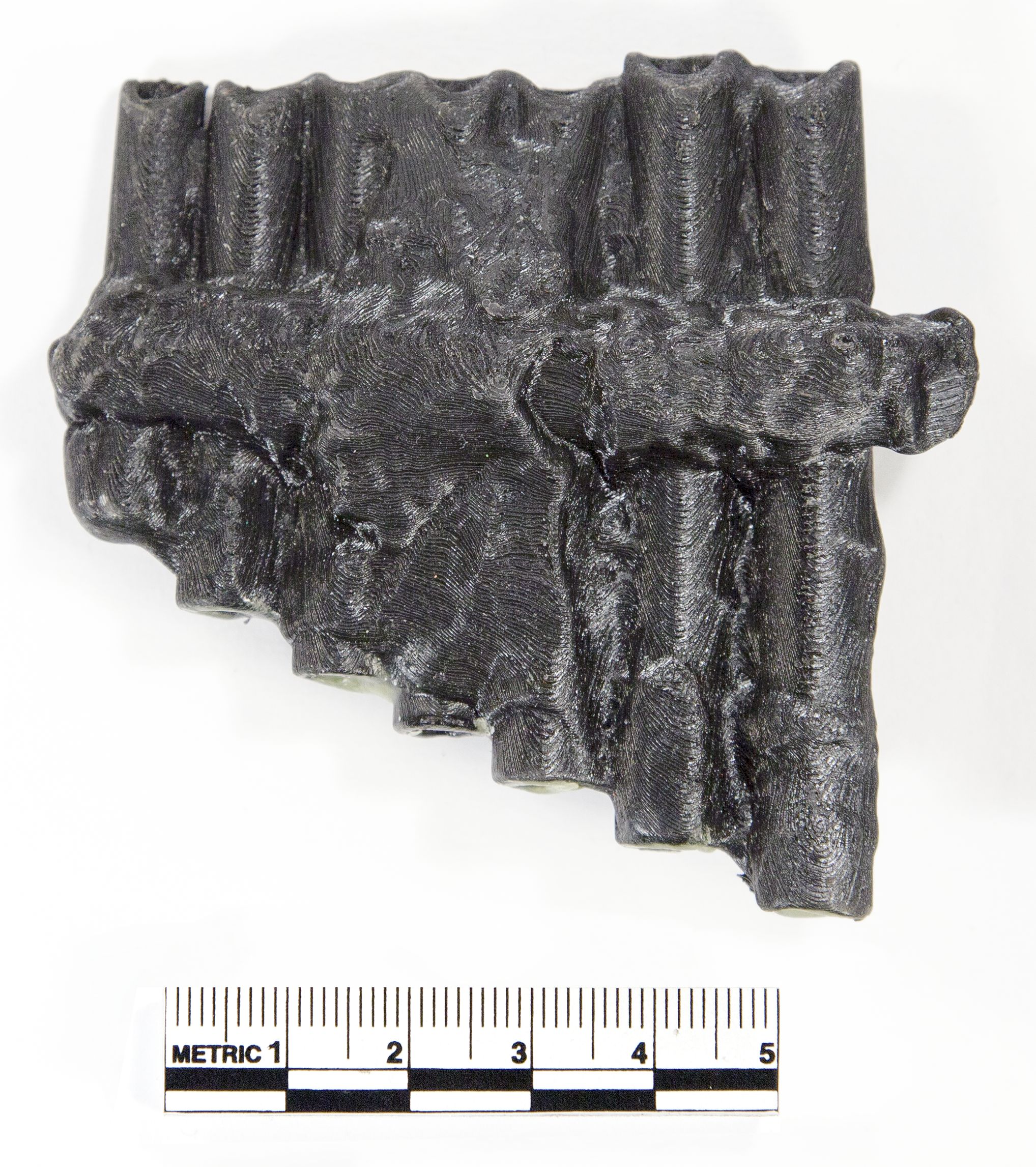
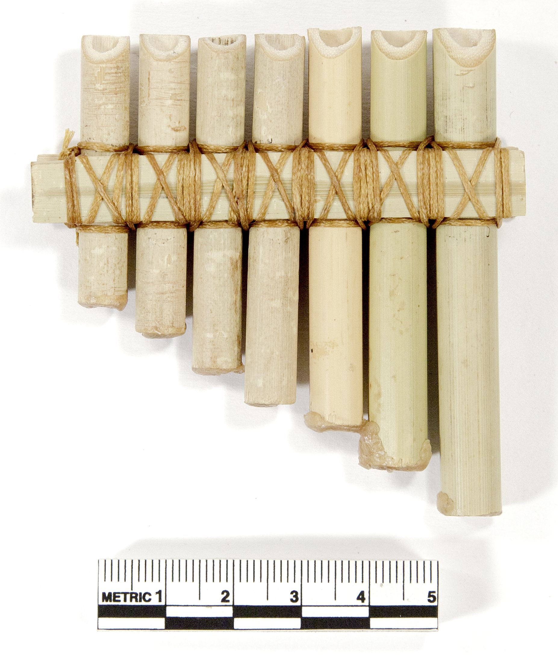
The individual parts of the original panpipes (UC33270) were loosely consolidated resulting in a very fragile object (Figure 7a). Careful handling ensured minimal scan alignment issues later in the workflow. Damage to the ends of the tubes had made the whole object incomplete. To make the reconstructed instrument playable, therefore, the tubes underwent significant reconstruction at the 3D modelling stage. Examination showed that damage had not been even, with at least a part of tubes 1–6 at their likely original length (Figure 7b). The 3D scan measurement of each tube length at the maximum was therefore used as the total reconstructed tube length. The seventh tube was intact at the far end, and its length could be reconstructed from the putative alignment of the mouth end with the end of the sixth tube. The inner diameters of the tubes were taken from measurements of the original artefact. Tubes of the correct diameter were added within Studio that were aligned with the surviving tubes, edited to length, and then combined with the model. This simplified the process and removed the need for further blending and modelling work in Mudbox. The eventual replicas in PLA and bamboo are shown in Figures 8a and 8b.
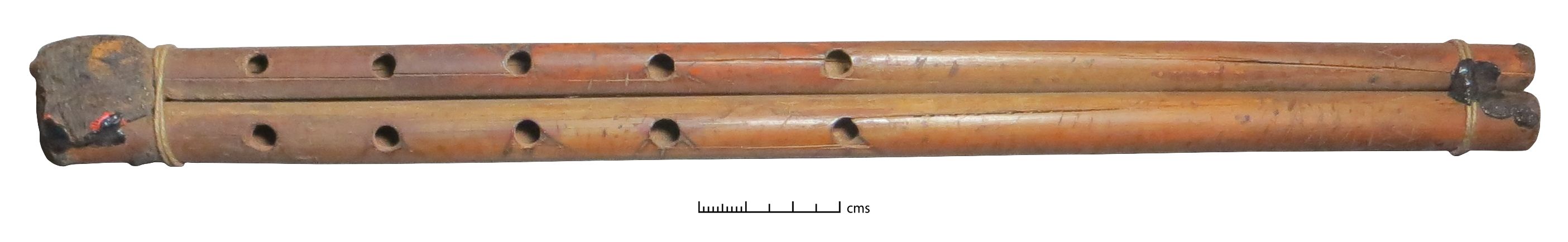
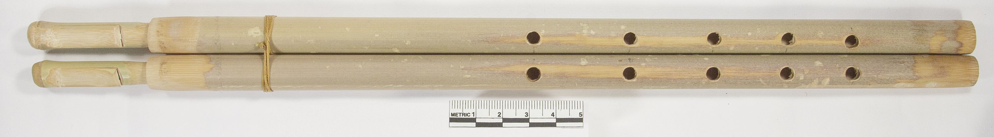
The inner diameter of the tubes of the double pipes (UC59260, original shown in Figure 9a and replica in Figure 9b) were reconstructed in a similar manner, and cracks in the tubes of the original object were filled in during the 3D modelling process.
The 3D model of each object is available for download as an .stl file for re-creation of the objects, in Appendix 1.
The composition of the objects was evaluated using a Niton XL3T pXRF analyser on the unprepared metal surfaces. The objects were all in good condition, with metallic surfaces and no corrosion products, so the results may be treated semi-quantitatively (see Lutz and Pernicka 1996). Alloys were classified using the alloy categories from Bayley and Butcher 2004, table 5. Each object was made of a slightly different combination of metals, and there was not sufficient funding available to use an individual metal recipe for each replica object. There are also likely to be some differences between original composition and pXRF results, caused by post-deposition processes (Craddock et al. 2002, 120), so a composition identical to the original when it was made could not be achieved anyway. The alloy types used were chosen instead to reflect the broad composition and/or properties of the original alloys used.
The metal objects were divided into two groups; cymbals UC35797 and UC33269a–b, which from inspection of the originals are likely to have been made by forging (shaping a cut-out blank by hammering), and the rest of the metal objects, which were originally made by casting. All of the metal objects were made by craft practitioner and professional jeweller Justin Richardson.
Justin created the cymbal replicas for UC35797 and UC33269a–b using spun brass (Figure 10a–b shows the former with its original; Figure 6 shows the original of UC33269b). Measurements for the dimensions of the replicas were taken from the scan data. In this production method, a chuck (form) is made from solid wood, and a metal blank is sandwiched between this and a support to put pressure on the other side. The metal is lathe-spun and forced against the chuck to create the correct shape. The process hardens and strengthens the metal object produced. The process of making spun metal objects was known in the Roman period and it was used particularly for vessels (Mutz 1972 is a detailed treatment). It is possible that the original cymbals were made in this way, especially since concentric engraved lines on the original objects are likely to have been produced on a lathe. Yet the basic form might also have been made by simply hammering the metal blank over a prepared chuck, which would have a similar effect.
The metal objects for casting were printed using wax filament suitable for the 'lost wax' casting process. A mould was then made around the wax build, and the wax melted away by filling the mould with molten metal. This is the same casting process known from antiquity and so, following the production of the 3D wax model, mimics the original production method closely. The method also ensures minimum shrinkage and thus a close match between the dimensions of the originals and the replicas (see Table 1). As noted above, however, several objects had to be thickened at the 3D modelling stage to ensure a successful cast, and so the replicas created in this manner will be slightly less accurate. The alloy used was silicon bronze. While this alloy would not have been available in the Roman period, the alloy mimics the properties of high tin bronze or 'bell metal' (c. 20% tin), which judging from the compositional analysis was used for several of the metal bells (UC8976, UC33261, and possibly UC30389, see Table 1). In particular, there is a good match in the acoustic damping properties of the metal, which is important for the sound quality of metal bells (Ketut Gede Sugita et al. 2011; see also Rossing 1984). It is therefore an affordable alternative to the use of high tin bronze for bell replicas. The originals and replicas of these objects are shown in Figures 11–16 (only one bell on bracelet is shown, as the others are very similar).
Figures 11-15: Scroll through images or click to expand and to view extended image captions.


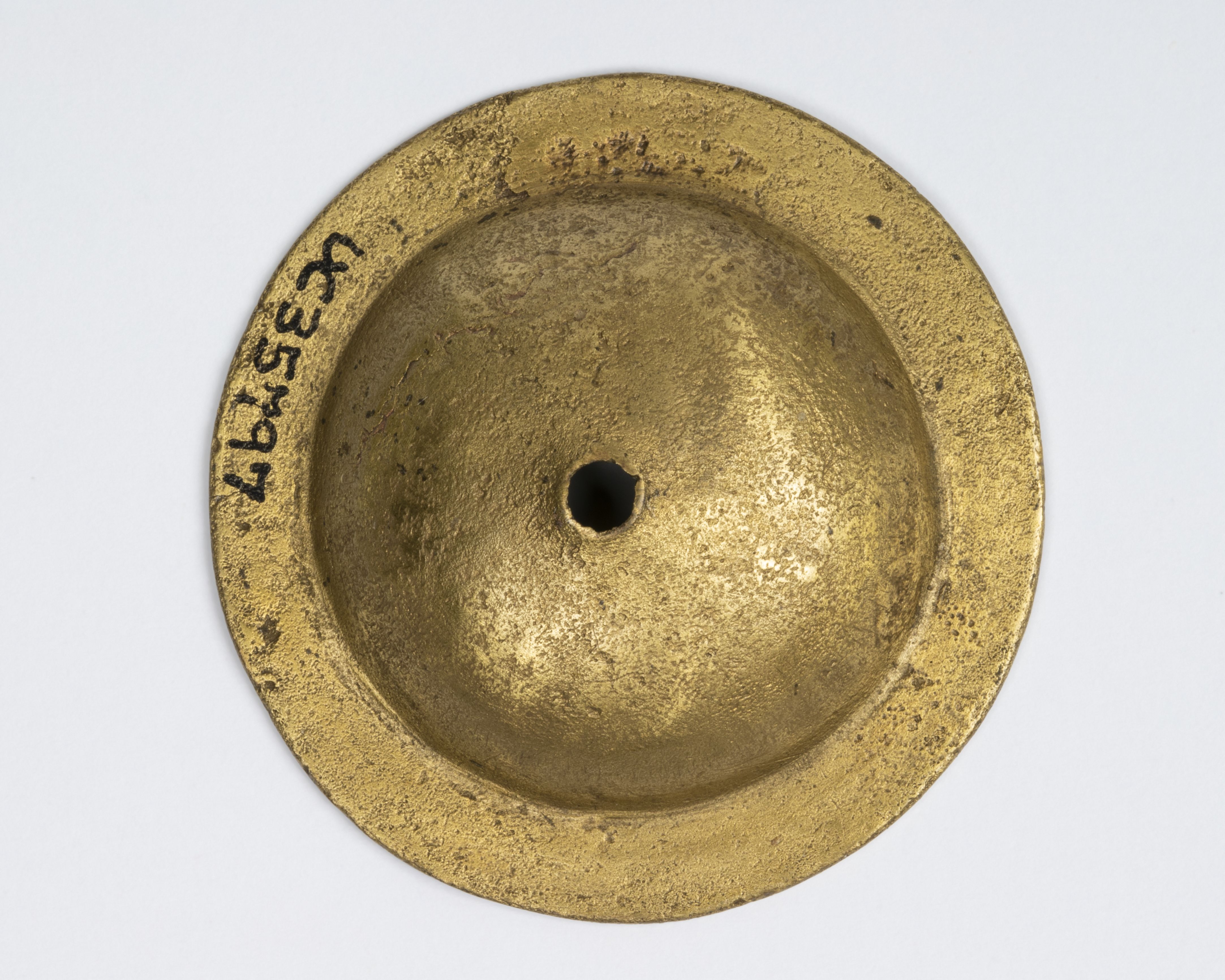
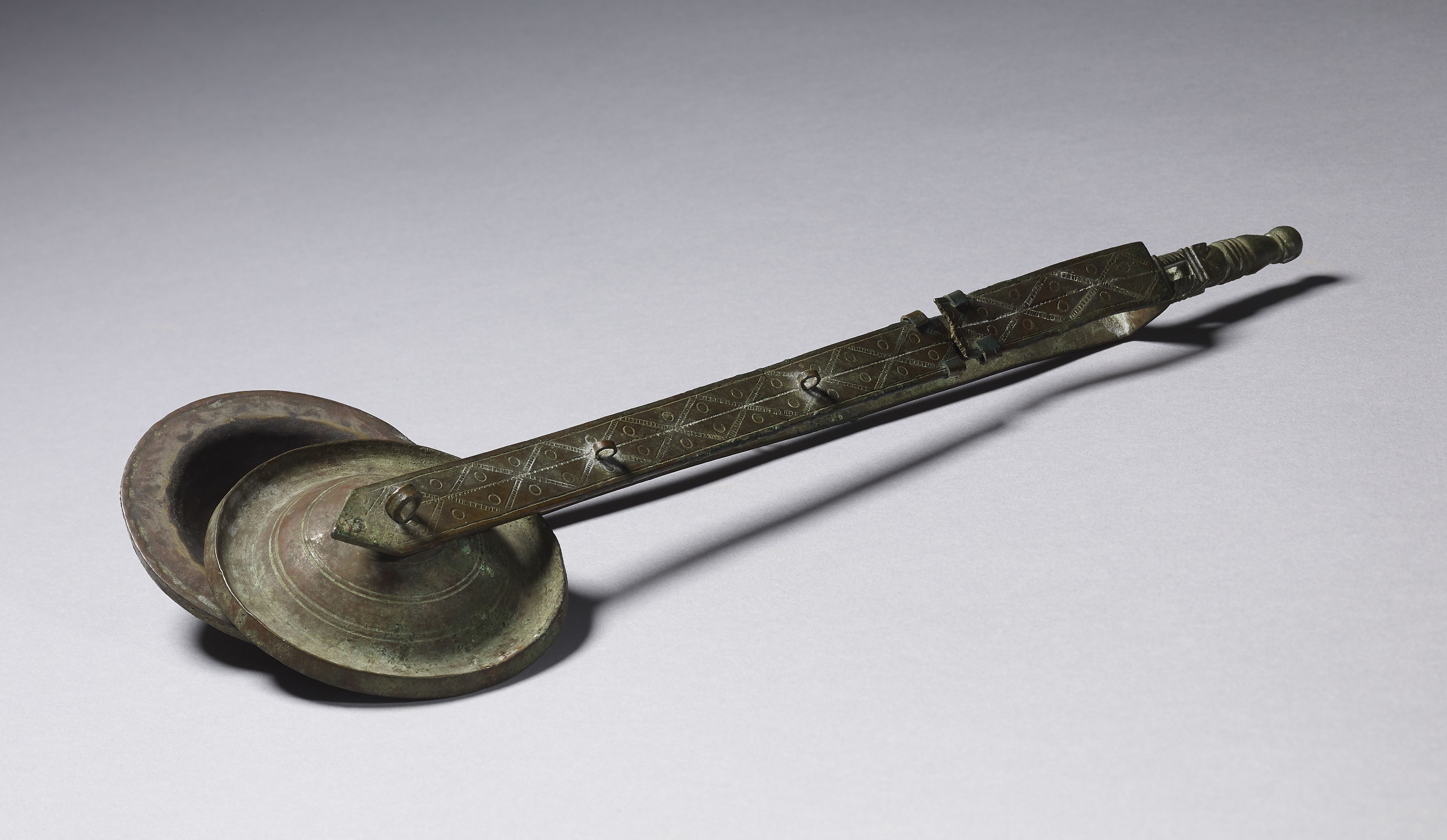
From inspecting the original of UC35798 (Figure 16a), we could see that the top surface of the cymbal had worn thin where it had rubbed against another surface, so it will originally have been mounted on a handle with another cymbal to make a pair of crotals. Petrie mentions such handles having been found on cymbals from Lahun in his publication of everyday objects found in his excavations in Egypt (Petrie 1927, 58, although none are extant in the UCL collection). Cymbals mounted on handles are also depicted in numerous Roman and late Antique period visual sources (a new study of these is currently being undertaken by Daniela Castaldo; see also Hickmann 1949a, 472–77 for multiple examples) and there are also a number of extant complete instruments and handle fragments (e.g. Ziegler 1979, 68–70, cat. nos 92–93; Hickmann 1949a, 32–37, acc. no. 69261; Nauerth 1996, 118–19, cat. nos 14a and 14b). We reconstructed the handle (Figure 16b) using an extant example from the British Museum as a model (acc. no. EA26260; Anderson 1976 cat. no. 27). This original object is shown in Figure 17.

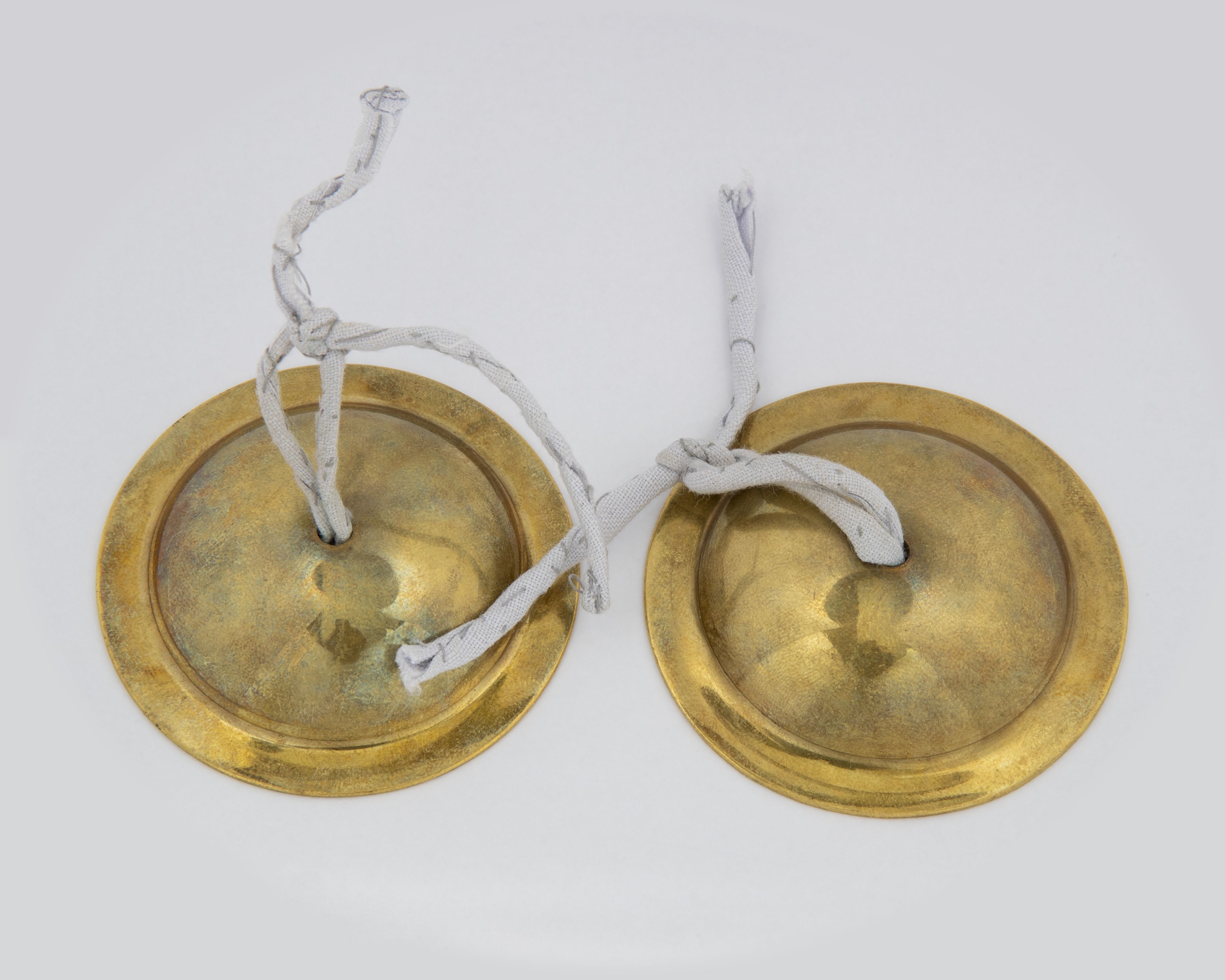
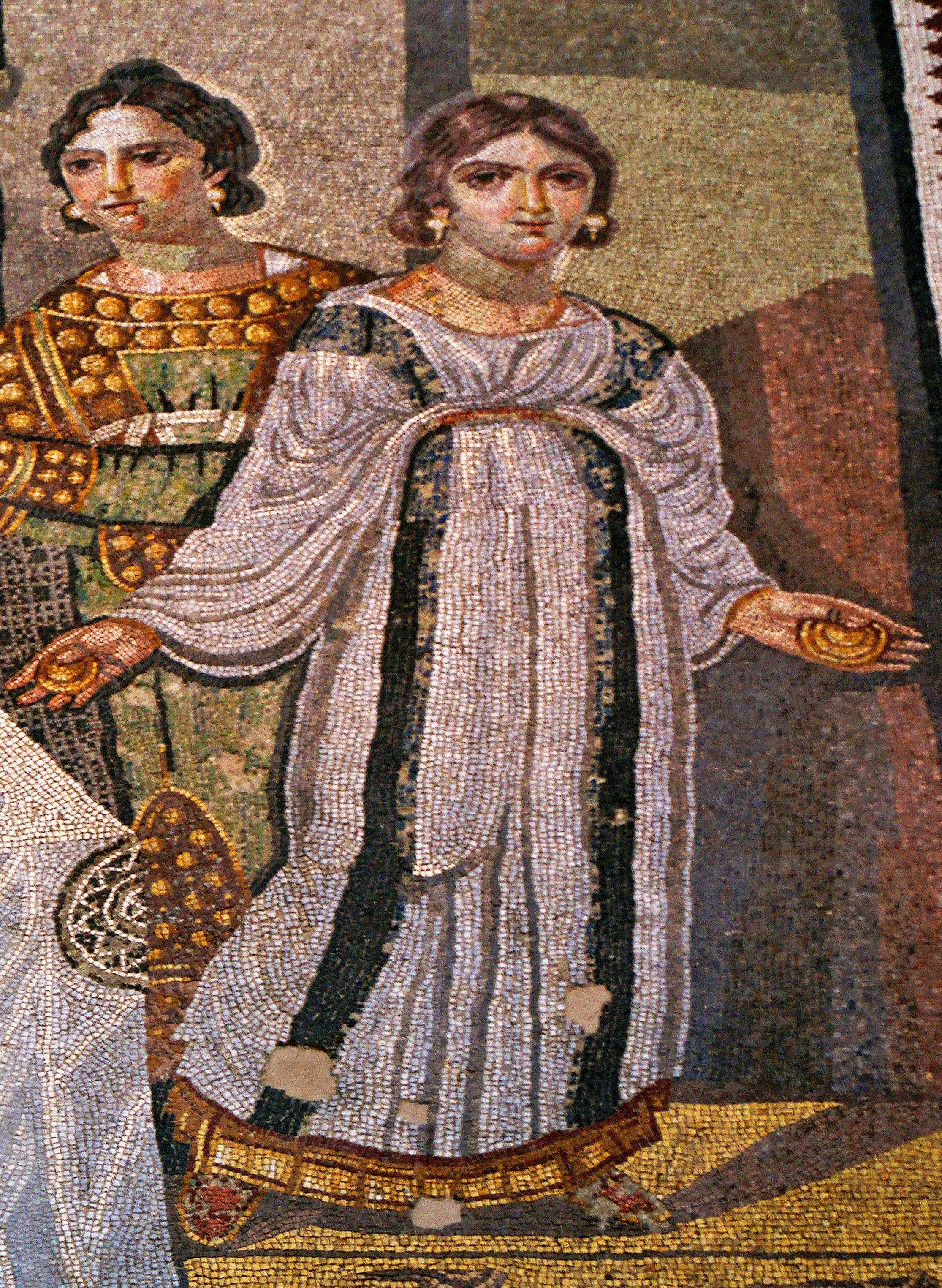
Cymbal UC35797 did not have visible wear to the surface (Figure 10a), and could possibly therefore have been part of a pair of small cymbals without metal handles, and was reconstructed as such (Figure 10b). A mosaic from Mariamin, Syria, of 4th century AD date, showing pairs of small cymbals tied around the fingers on each hand, provided a model to follow (Figure 18). The mosaic also shows that a set for playing would probably have comprised two pairs, one for each hand, but only a single pair was re-created. For the material for the ties, we have chosen linen, based on another British Museum example of cymbals tied together with a linen cord (acc. no. 6373, Anderson 1976, cat. no. 22). These cymbals are much larger than the Petrie Museum examples (c. 15cm across), and would have been held one in each hand, so we have not followed their example in the precise way the linen cord is used, but only in the use of linen as a likely material.
There are three bells that are suspended on bracelets. Wear marks on the artefacts confirm that these are original associations (see Swift et al. forthcoming for more details). Since iron was used for these bracelets, low-carbon steel was used to forge the replica bracelets. These were made to the same dimensions as the originals, using measurements taken from the original artefacts. Decoration on two of the originals was not especially well preserved, but could be re-created using additional evidence of better surviving examples with similar decoration (for example, Crummy 1983, cat. nos 1715 and 1721).
For bells UC58536 (shown in Figure 11a), UC58538 (shown in Figure 19), and UC58540, the original clappers in copper alloy survived, so copper alloy was used for the replicas. As regards the other bells, the evidence more widely available suggests that both copper alloy and iron were used as clapper materials (Bénazeth 1992, 237–45; Hickmann 1949a, 37–65), and so we have chosen to maintain this variety in the replicas (see Table 1 for details; low-carbon steel was the nearest available equivalent to iron). For these bells, we have no information on which part of the bell wall was struck by the clapper, but drawing on the evidence of the examples with intact clappers, it appears that clappers were normally of a length that would strike the bottom edge of the bell (Figure 19), and so this is the norm applied to all the bell replicas. Finally, one bell (UC33261, shown in Figure 15a) had two additional ring fittings attached to the ring that was cast integrally with the bell, so similar ring fittings were also added to the replica (Figure 15b).
| Cymbals/Crotals | ||
|---|---|---|
| UC35797 Original | UC35797 Replica | |
| Description | Single cymbal, flat rim | Pair created from single original |
| Pitch* | Example with label Primary D7, 2323 Hz; Secondary G8 (hitting singly with stick). Example without label Primary C#7, 2244 Hz; Secondary F#8 (hitting singly with stick). Multiple frequencies when clashed together, see Figure 20. | |
| Dimensions mm | Max. diameter of cymbal 53 | Max. diameter of cymbal 52 |
| Cymbal material | Brass (Zn c. 15%) | C260 Cartridge Brass |
| Handle material | Not known | C377 Forging Brass |
| Weight | 16g | 16g and 17g |
| Notes | Forged? | Spun on lathe |
| UC35798 Original | UC35798 Replica | |
| Description | Single cymbal | Pair created from single original Initial casting failed, wall of 3D model thickened to a minimum of 0.8mm to achieve successful casting. Handle based on British Museum acc. no. EA26260 (Anderson 1976, cat. no. 27). |
| Pitch | Not known | Octaves 7–9 predominate* |
| Dimensions mm | Max. diameter of cymbal 56. Length of EA26260 handle 246. | Max. diameter of cymbal 57. Length of handle 241 |
| Cymbal material | Copper/brass (Zn c. 3.5%) | Silicon Bronze C655A |
| Handle material | Not known | C377 Forging Brass |
| Notes | Cast | Cast |
| UC33269a–b Original | UC33269a–b Replica | |
| Description | Pair of cymbals, slightly thicker, upturned edges | Edges thickened as on originals. Simple metal U-shaped handles added based on Petrie 1927, 58: 'long, springy handles'. |
| Pitch | Not known | Octaves 6–9 predominate* |
| Dimensions mm | Max. diameter of cymbal. UC33269a 59. UC33269b 57. | Max. diameter of cymbal 59. Length of handle 300, total length 321 (parallel for length, Ziegler 1979, cat. no. 93 with total length 321) |
| Cymbal material | UC33269a Copper/brass (Zn c. 4.4%). UC33269b Bronze (Sn c. 3%) | C260 Cartridge Brass |
| Handle material | Not known | C377 Forging Brass |
| Notes | Forged (hammered), lathe-turned | Spun on lathe |
| Bells on bracelets | ||
| UC58536 Original | UC58536 Replica | |
| Description | Bell on bracelet with flat square terminals, one missing | Bracelet reconstructed with two flat square terminals. Bell wall thickened by 0.5mm |
| Pitch | Primary note D#8 | Primary note B8, 7915 Hz; Secondary notes D#10, E10 |
| Dimensions mm | Max. inner diameter of bracelet 34. Max. inner diameter of bell 17. | Max. inner diameter of bracelet 34. Max. inner diameter of bell 17 |
| Weight | 6g (bell only) | 8g (bell only) |
| Bell material | Bronze, leaded (Sn c. 4.8%) | Silicon Bronze C655A |
| Clapper material | Cu alloy | Cu alloy |
| Bracelet material | Iron | Low carbon steel (LA-C) |
| Notes | Cast | Clapper made from looped folded rod and attached with thin metal strip, as original |
| UC58538 Original | UC58538 Replica | |
| Description | Bell on bracelet with terminals missing | Terminals reconstructed as flat cuts to the ends of the bracelet. Bell wall thickened by 0.5mm |
| Pitch | Primary note F#7, secondary note B8 | Primary note G#8, 6765 Hz; Secondary note A8 |
| Dimensions mm | Max. inner diameter of bracelet 30. Max. inner diameter of bell 17. | Max. inner diameter of bracelet 30. Max. inner diameter of bell 17 |
| Weight | 6g (bell only) | 9 g (bell only) |
| Bell material | Bronze (leaded) (Sn c. 5.2%) | Silicon Bronze C655A |
| Clapper material | Cu alloy | Cu alloy |
| Bracelet material | Iron | Low-carbon steel (LA-C) |
| Notes | Cast | Cast |
| UC58540 Original | UC58540 Replica | |
| Description | Bell on bracelet with central disc | As left. Bell wall thickened by 0.5mm |
| Pitch | Primary note F#8 | Primary note G#8, 6546 Hz; Secondary note C#10 |
| Dimensions mm | Max. inner diameter of bracelet 29. Max. inner diameter of bell 17. | Max. inner diameter of bracelet 29. Max. inner diameter of bell 17. |
| Weight | 13g (bell only) | 10g (bell only) |
| Bell material | Bronze, leaded (Sn c. 6%) | Silicon Bronze C655A |
| Clapper material | Cu alloy | Cu alloy |
| Bracelet material | Iron | Low-carbon steel (LA-C) |
| Notes | Cast | Cast |
| Other bells | ||
| UC8976 Original | UC8976 Replica | |
| Description | Decorated with Bes mask. Remnant of loop for clapper attachment present inside. | Engraved decoration added to crown |
| Pitch | Not known | Primary note F7, 2828 Hz; Secondary notes F#8 and D9 |
| Dimensions mm | Max. inner diameter of bell 47 | Max. inner diameter of bell 47 |
| Weight | 128g (without clapper) | 130g (approx. without clapper) |
| Bell material | High Tin Bronze leaded (Sn c. 19%) | Silicon Bronze C655A |
| Clapper material | Not known | Cu alloy |
| Notes | Cast. Wear on rear loop confirms swung side-to-side. | Damage caused by wear replicated in casting process |
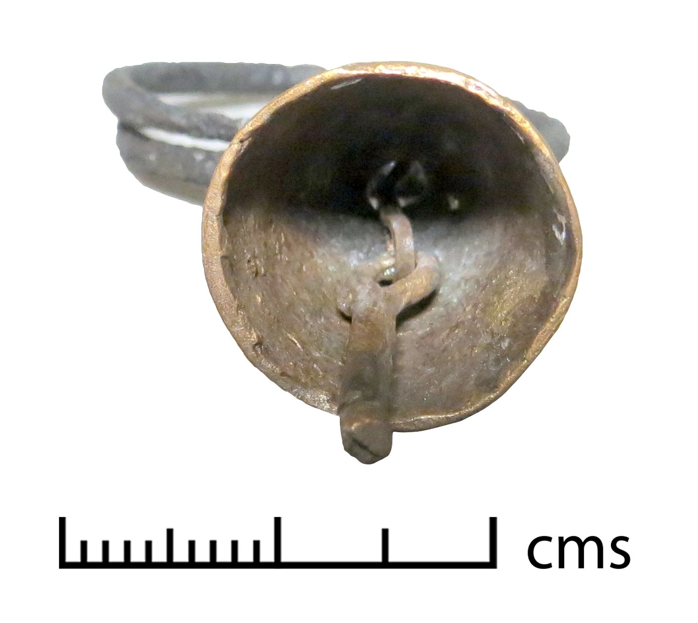
| UC30389 Original | UC30389 Replica | |
| Description | Rumbler bell with evil-eye motif | Initial cast failed as wall too thin. 3D model thickened to 1.2mm inside for successful cast |
| Pitch | 'about middle B and C' (Petrie 1927, 58 no. 301–2) | Primary note B6, 1967 Hz; Secondary note C7 |
| Dimensions mm | Max. horizontal diameter of bell | Max. horizontal diameter of bell |
| Weight | 46g (without pellet) | 48 g |
| Bell material | Bronze (Sn c. 15%) | Silicon Bronze C655A |
| Pellet material | Not known | Cu alloy ball |
| Notes | Cast | Cast |
| UC35794 Original | UC35794 Replica | |
| Description | Soldered loop at top | Loop cast in with bell body. In the original, a copper alloy wire is wound around the loop. This detail has not been replicated. |
| Pitch | Not known | Primary note G8, 6320 Hz; secondary notes G#8, C10 and C#10 |
| Dimensions mm | Max. inner diameter of bell 27 | Max inner diameter of bell 27 |
| Weight | 51g (without clapper) | 51g (approx. without clapper) |
| Bell material | Bronze, leaded (Sn c. 10%) | Silicon Bronze C655A |
| Clapper material | Not known | Low carbon steel (LA-C) |
| Notes | Cast | Cast |
| UC33261 Original | UC33261 Replica | |
| Description | Two suspension loops attached at top | Two suspension loops re-created and added |
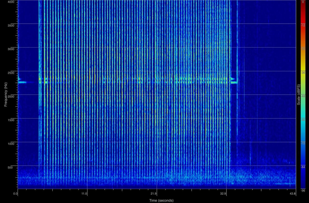
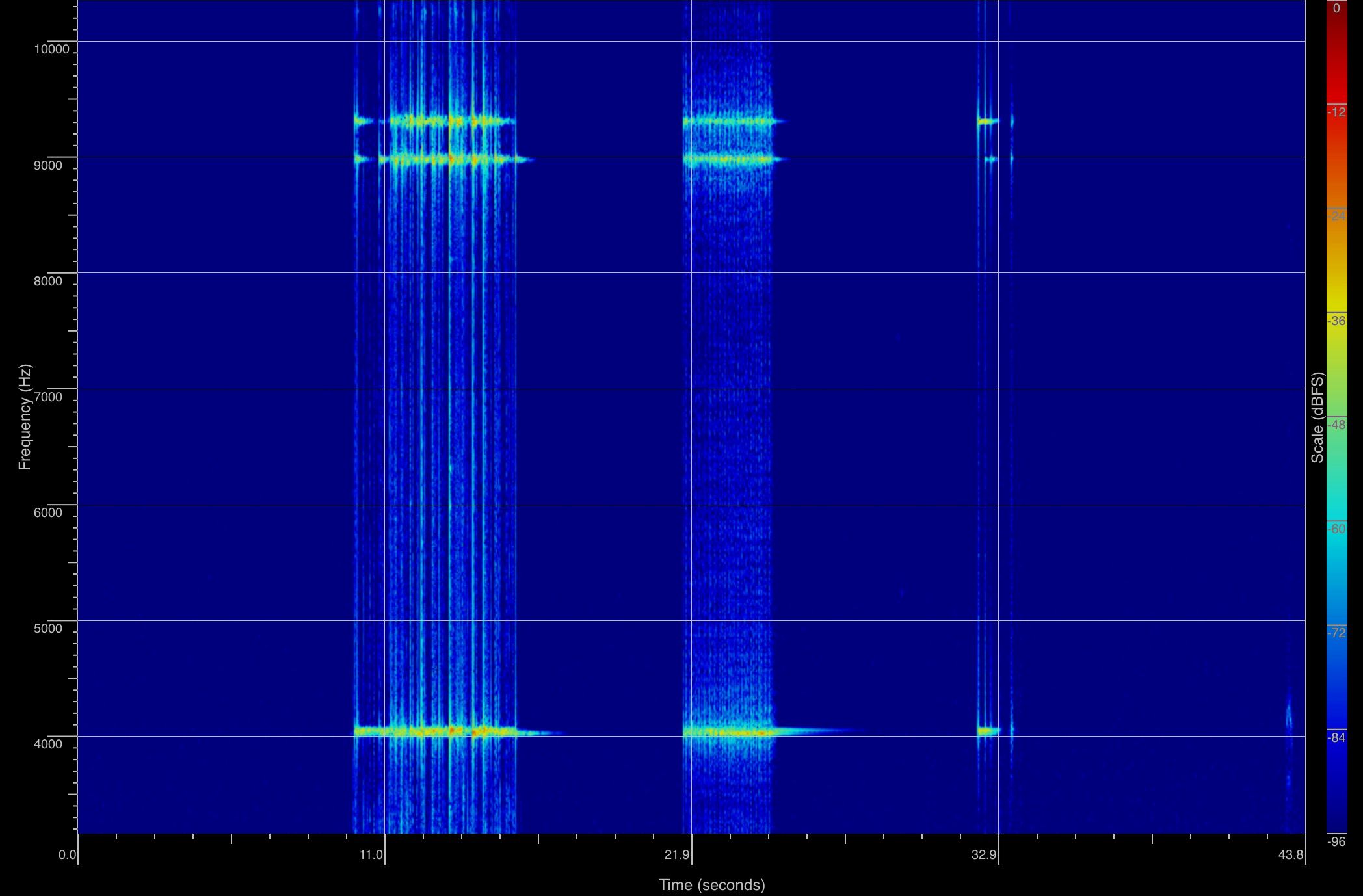
| Pitch | Not known | Primary note B7, 4040 Hz; secondary notes C#9 and D9, see Figure 21 |
| Dimensions mm | Max. inner diameter of bell 33 | Max. inner diameter of bell 33 |
| Weight | 36g (without clapper) | 38g (approx. without clapper) |
| Bell material | High Tin Bronze (leaded) (Sn c. 19%) | Silicon Bronze C655A |
| Clapper material | Not known | Low carbon steel (LA-C) |
| Notes | Cast | Cast |
* The pitch of the original objects could be determined in comparatively few cases; either bells that had an intact clapper and so involuntarily produced a note during normal museum handling, and objects whose pitch was documented by previous researchers, at a period when museum objects had fewer restrictions concerning handling. For the replicas, pitches are given as frequencies in Hz, and as approximations to the nearest tempered semitone using A440 as the standard. Bells produce more than one frequency, but usually with an identifiable dominant (primary) note, and sometimes lesser notes are also discernible (secondary, etc.). Crotals and cymbals clashed together produce multiple frequencies simultaneously, so a single value cannot be identified for these. Recording of replica frequencies took place outdoors on 25/06/2018, in weather conditions of 22°C and 55% humidity, using apps SpectrumView 2.2 and PitchAnalyzer 6.0. SpectrumView has the benefit of displaying the frequencies graphically and in relation to sound levels, so that it is possible to confirm which frequencies predominate in the case of instruments that produce multiple prominent frequencies.
| UC34972 | UC34972 replica | |
|---|---|---|
| Description | Bird-shaped moulded rattle, containing clay pellets. Head missing | Head added in 3D modelling process. Made in three-part mould with separate head section. |
| Material | Earthenware coated in white slip | Earthenware 'Sanded Etruscan Red' (see below), coated in white slip |
| Dimensions | Max. width 56mm | Max. width 57mm |
| Weight | 108g | 110g |
| UC65087 | UC65087 replica | |
| Description | Pointed rattle, handmade, complete | Made in two-part mould |
| Material | Earthenware (Nile silt) with plant stem temper | Earthenware 'Sanded Etruscan Red' (see below), with chopped straw temper |
| Dimensions | Length 85mm, diameter 58mm | Length 87mm, diameter 58mm |
| Weight | 98g | 134g |
| UC71557 | UC71557 replica | |
| Description | Half piece of moulded rattle | Made in two-part mould |
| Material | Earthenware | Earthenware 'Sanded Etruscan Red' (see below) |
| Dimensions | Diameter 34mm wall thickness c. 3mm | Diameter 36mm wall thickness c. 3–4mm |
| Weight | Not recorded since object incomplete |
The ceramic rattles in the Petrie collection are listed in Table 2 and are shown with their replicas in Figure 3a/3b, Figure 4a/4b and Figure 5a/5b. (It should be noted that rattles produce multiple frequencies simultaneously, so a single value cannot be identified, and this information is not included in the table.) The replicas were made by George Morris and Georgia Wright. The original objects have not been subject to compositional analysis. One of the objects, however, has its composition identified in the Petrie online catalogue as Nile silt, an alluvial clay that was commonly used for ceramic artefacts in Pre-Dynastic, Dynastic, Hellenistic, and Roman Egypt (UC65087). The clay composition of several artefacts manufactured from Nile silt has been investigated in scholarly research, and a commercial earthenware clay body was chosen that approximated to this composition (see Table 3) and used for all the object replicas. Grains of sand were visible in the clay matrix used for the original objects, and so a clay tempered with sand was chosen (10% 40/90 sand giving a medium-coarse texture). The pointed rattle (UC65087) also showed evidence of vegetable temper in the form of impressions left on the surface of the clay where an organic material had burned away during firing. Chopped straw temper was therefore also added to the clay used for the replica of this object in particular.
| Principal Minerals | 'Sanded Etruscan Red' from Potclays Ltd (%) Becky Otter, pers. comm. | Nile Silt Predynastic period, Sample HK1* Redmount and Morgenstein 1996, table 2 (%) | Nile Silt Predynastic period, Sample HK2* Redmount and Morgenstein 1996, table 2 (%) |
|---|---|---|---|
| SiO2 | 58.29 | 54.4 | 58.8 |
| Al2O3 | 22.63 | 15.3 | 15.7 |
| Fe2O3 | 6.89 | 9.19 | 11.2 |
| MgO | 0.85 | 2.75 | 3.10 |
| CaO | 0.44 | 4.83 | 4.37 |
| K2O | 1.48 | 1.56 | 1.31 |
| Na2O | 0.07 | 1.74 | 1.53 |
| TiO2 | 1.23 | 1.65 | 2.07 |
| P2O5 | 0.07 | 0.4 | 0.31 |
| MnO | - | 0.14 | 0.18 |
*HK1 is straw-tempered, HK2 untempered, see Redmount and Morgenstein 1996, table 1.
Test firings were used to establish the shrinkage rate of the chosen clay at the desired temperature (9.4%) and the 3D models were enlarged in size accordingly before printing in ABS thermoplastic. The chosen firing temperature was 700°. This is rather lower than the firing temperatures suggested for Nile silt clays (a minimum temperature of 750°: The Levantine Ceramics Project, see also Hamdan et al. 2014, 987). However, it was chosen based on the opinion of a craft practitioner who had examined the appearance of the original objects and who suggested that UC65087 in particular appeared to be rather under-fired (Eric Hall, pers. comm.). The qualities of test samples fired at a range of different temperatures were also taken into account.
Moulds were made for the objects in plaster of Paris using the ABS 3D prints coated in slip. For the nut-shaped rattle, with only one-half extant, two prints were made and joined using clay before the mould-making stage. Two-piece moulds were used for the replicas of UC71557 and UC65087, while for UC34972 a separate head part was also required in addition to the two main horizontal halves of the mould. A break in the original object, where the head is missing, shows that there was no vertical join and so this was felt to be the most likely original method, rather than the use of two moulds dividing the object vertically. It was evident from inspection of the originals that UC34972 and UC71557 were originally made in moulds. Although the original of UC65087 had probably been made by hand without the use of a mould, it was decided that using a mould would better preserve the dimensions of the original object, and so these were used for all of the ceramic objects.
As noted above, it was difficult to evaluate the wall thickness for the bird rattle and pointed rattle (UC34972 and UC65087) so the thickness of the clay used was based on the information from the nut-shaped rattle where the original was c. 3mm thick. The bird rattle appeared to be of a similar thickness, at least in the area around the hole in the base of the object. Slightly thicker clay (c. 5mm) was rolled out, which then was compressed slightly as it was pressed into the moulds, resulting in a thickness of approximately 3–4mm.
There was information from the bird rattle original concerning the appearance of the pellets inside, which were partly visible through the hole in the bottom of the object and, fortuitously (although not from the museum's perspective), one of these fell out when the object was being examined, allowing its shape to be noted before it was placed back inside. Similar small oval pellets about 0.5–0.8mm long were added to the halves of each mould before these were pressed together to make each complete object. Since there was no information available concerning the likely quantity of pellets inside each rattle, a number of different replicas were produced for each original using different quantities of pellets. Those used in sound recording are shown in Figures 3b, 4b and 5b.
The objects were finished by hand with the use of wooden tools to replicate the decorative detail used. The bird replicas were also coated in white slip as this had been used to coat the reddish clay body of the original object. The objects were then fired in a non-vented electric kiln on a drying - slow biscuit programme of 10° per hour for 15 hours, then 30° per hour to 700°.
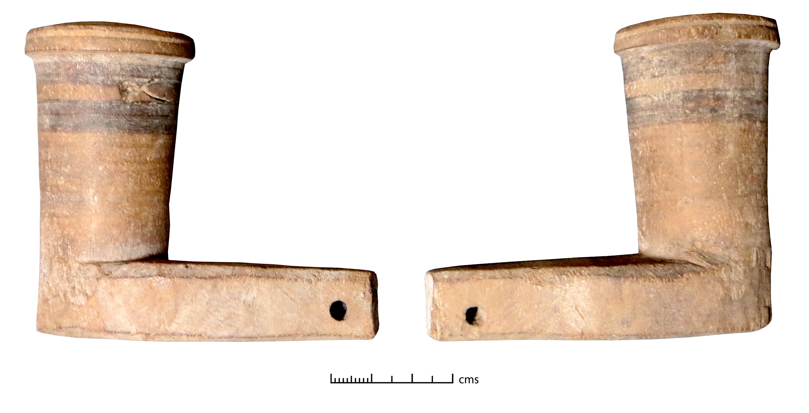
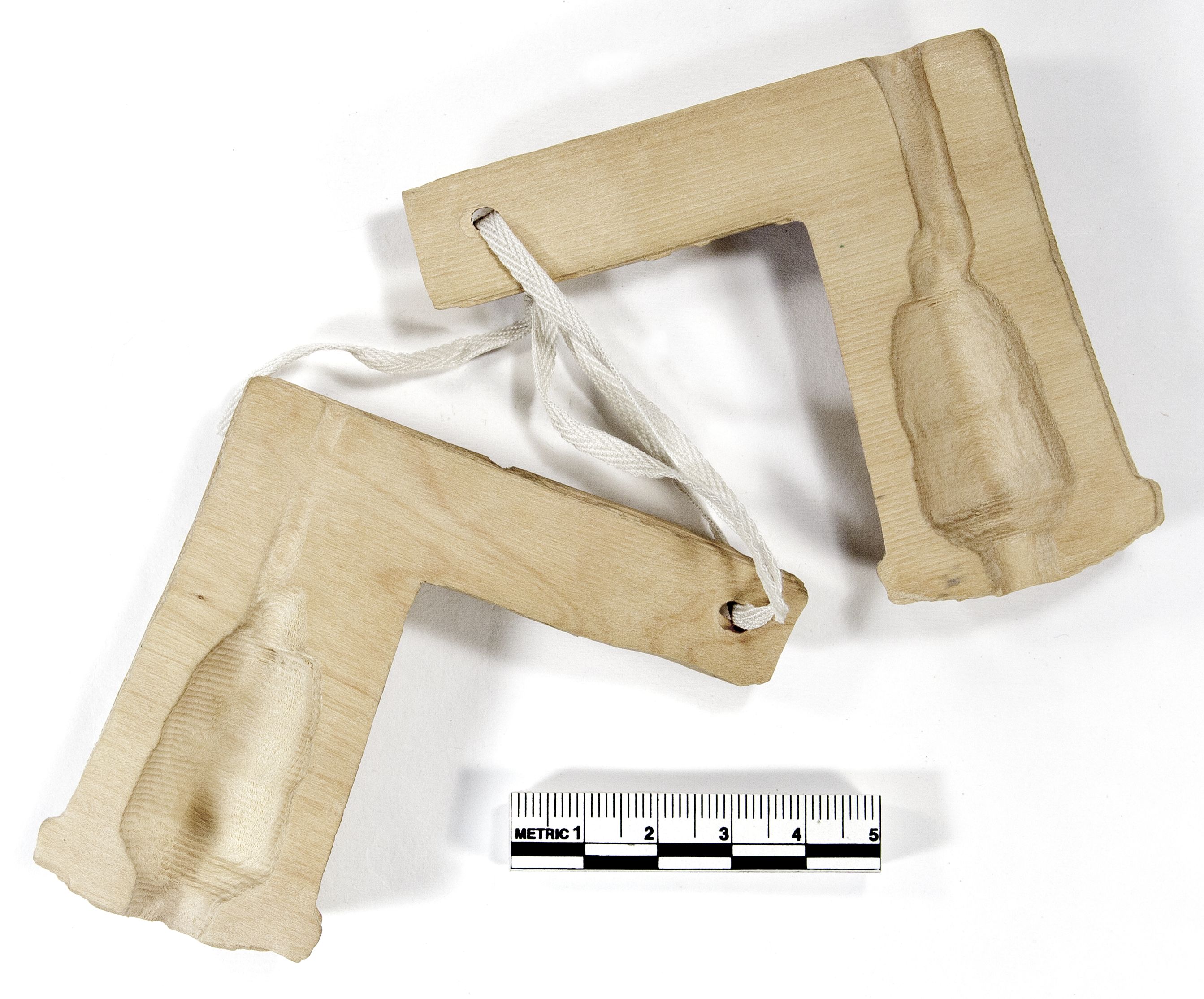
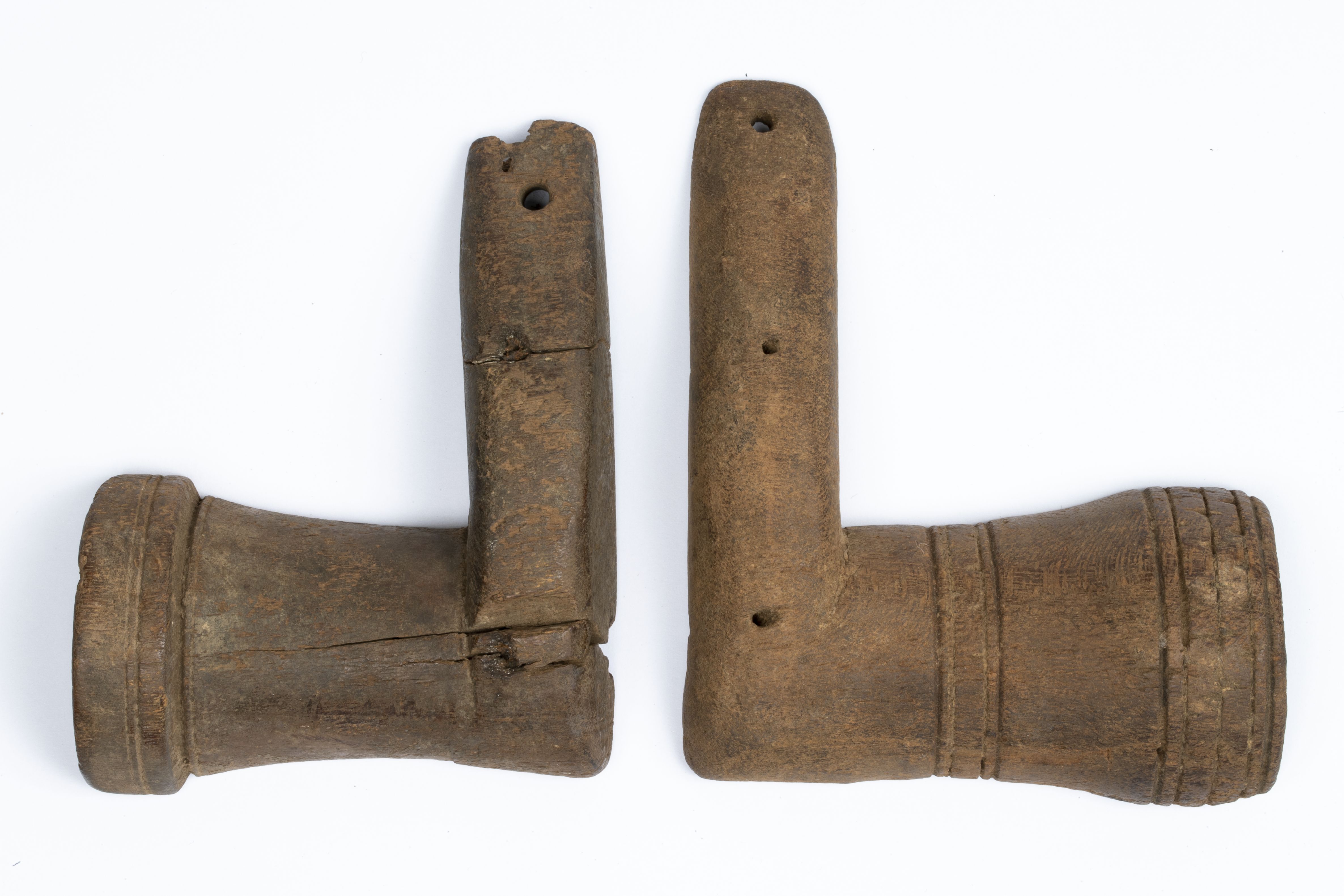
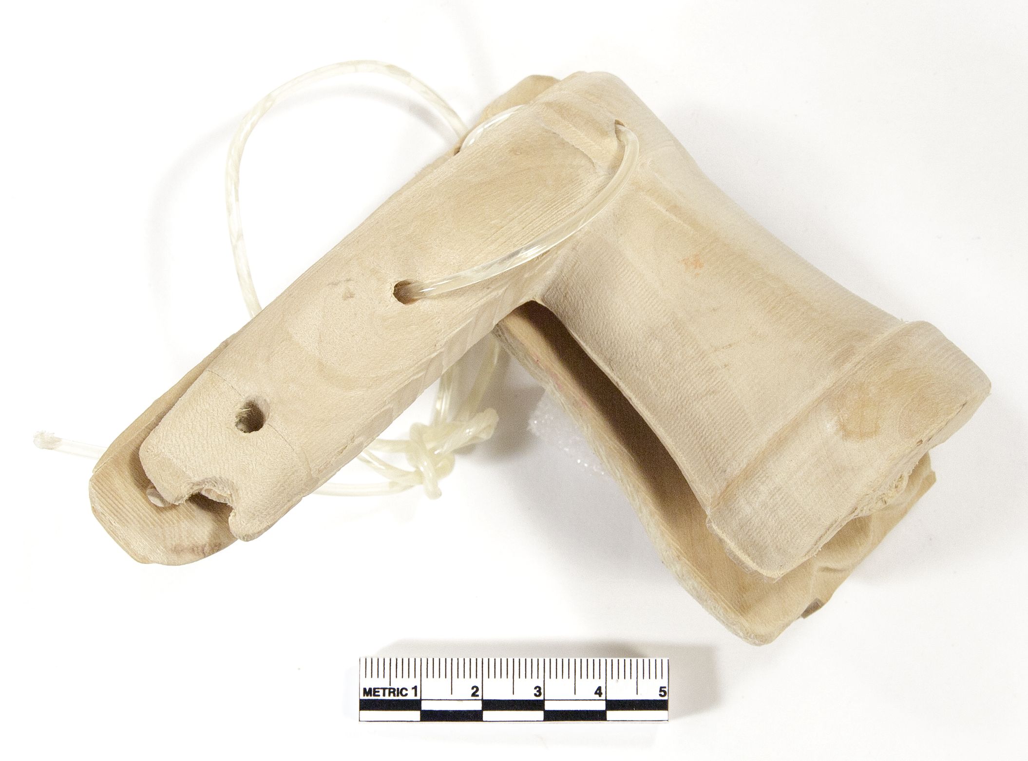
The two sets of wood clappers were the most straightforward to produce since each half could be cut out in wood by sending 3D scan data directly to a wood router, thus preserving the original dimensions of the objects very closely. Details are given in Table 4 (it should be noted that clappers produce multiple frequencies simultaneously, so a single value cannot be identified, and this information is not included in the table) and originals and replicas are shown in Figures 22a/22b and Figures 23a/23b. The replicas were made by Keith Greenhow, Daniel Knox and Julien Soosaipillai. The commonest wood used in the Roman period for small turned objects is European boxwood; however, this species is very slow growing, and so large pieces of timber rarely become available. We were not able to source large enough pieces to match the dimensions of the objects, and so a New World species with similar properties, castello boxwood, was used instead. The other question for this object type concerned whether the two halves of the clapper had originally been joined together and, if so, how. Similar modern objects used in Turkey are not joined (Kevin Dawe, pers. comm.) and this seemed most likely for the clapper set with a single large hole through each handle end (UC59603 and UC59604). Experimenting with the replicas of these objects suggested that tying the two parts together using the hole did not hold the objects in the correct tension for them to be used effectively held in one hand. It was probably used instead for a long, loose tie so that the objects did not become separated from one another. Conversely, the original of UC71305a–b possessed matching pairs of small holes drilled diagonally through the object which proved suitable for joining the two halves. Although the wood router was not capable of creating these holes in the original cut, their position was easy to identify from indentations on the replica objects and they were drilled through using a narrow drill bit similar in dimensions to that of the original holes. Drawing on examples of historical musical instruments such as castanets (e.g. those displayed in the Oxford University Bate Collection), catgut (usually made from the intestines of ruminant animals) was selected as a joining material. When it was threaded through the pairs of holes, joining the two parts together, a very effective set of clappers was produced that could be operated with one hand.
| Wooden Objects | ||
|---|---|---|
| UC59603 | UC59603 replica | |
| Description | Foot-shaped clapper, pair with UC59609 | |
| Material | Wood | Castello boxwood |
| Dimensions | Diameter of semi-circular part 39mm; 'foot' length 82mm | Diameter of semi-circular part 39mm; 'foot' length 82mm |
| Weight | 22g | Not recorded |
| UC59609 | UC59609 replica | |
| Description | Foot-shaped clapper, pair with UC59603 | |
| Material | Wood | |
| Dimensions | Diameter of semi-circular part 39mm; 'foot' length 82mm | Diameter of semi-circular part 39mm; 'foot' length 82mm |
| Weight | 22g | Not recorded |
| UC71305(a) | UC71305(a) replica | |
| Description | Foot-shaped clapper, probably used as pair with UC71305(b) | |
| Material | Wood | Castello boxwood |
| Dimensions | Diameter of semi-circular part 49mm; 'foot' length 111mm | Diameter of semi-circular part 51mm; 'foot' length 106mm |
| Weight | 54g | 52g |
| UC71305(b) | UC71305(b) replica | |
| Description | Foot-shaped clapper probably used as pair with UC71305(a) | |
| Material | Wood | Castello boxwood |
| Dimensions | Diameter of semi-circular part 50mm; 'foot' length 113mm | Diameter of semi-circular part 50mm; 'foot' length 111mm |
| Weight | 49g | 63g |
| Reed Objects | ||
| UC33270 (tube lengths from 3D scan, inner diameter from caliper measurement of original) | UC33270 replica | |
| Description | Set of panpipes with 7 tubes | See Section 2.5 on 3D modelling for details of reconstruction made at that stage |
| Material | Reed, probably a phragmites species (Dorian Fuller, pers. comm.) | PLA print with beeswax, bamboo with beeswax |
| Dimensions | 1st tube length 70mm, inner diameter 6.3mm 2nd tube length 65mm, inner diameter 5.9mm 3rd tube length 58mm, inner diameter 5.6mm 4th tube length 54mm, inner diameter 5.1mm 5th tube length 49mm, inner diameter 5mm 6th tube length 44mm, inner diameter 4.6mm 7th tube length (reconstructed) 38mm, diameter 4.6mm (all inner diameters measured horizontally, at the maximum distance) | 1st tube length 70mm, inner diameter 6.0mm* 2nd tube length 65.5mm, inner diameter 5.9mm 3rd tube length 58mm, inner diameter 5.2mm 4th tube length 53mm, inner diameter 4.7mm 5th tube length 50mm, inner diameter 4.7mm 6th tube length 44.3mm, inner diameter 4.1mm 7th tube length 38.2mm, inner diameter 4.3mm |
| UC59260 | UC59260 replica | |
| Description | Double pipes, tubes joined together, 5 finger-holes in upper surface of each tube. No mouthpieces. | Cracks in original filled in on 3D model. New mouthpieces created. |
| Material | Reed | Bamboo |
| Dimensions | Length 318mm. Inner diameters 8mm and 9mm. | Length 316mm not including mouthpieces. Inner diameters 8mm and 9mm |
* Frequencies produced by each tube are given in Table 5.
The objects were printed in PLA, a biodegradable thermoplastic made from cornstarch. One set of panpipes was also SLA printed in photopolymer resin, which gives a more accurate result with, for instance, fewer external traces on the object of the printing process. However, there was no difference in the sounds produced by the PLA compared to the photopolymer set. The original of the double pipes was missing its separate mouthpiece parts and so the 3D print of the main sections of the flute could not be played directly. Replicas were also made in organic materials of both the double pipes and the panpipes, by Georgia Wright. Bamboo was used as a material as it proved difficult to source reeds that were sufficiently robust and of the correct diameter. Bamboo canes as close as possible to the correct external diameters were selected and the interiors were drilled out to match the diameters of the original instruments by selecting drill bits of appropriate size. The pipes were cut to the same lengths as the originals.
Initially the 3D printed panpipes only made a sound from the highest tube, which on the original was blocked with beeswax, and so also had a sealed end in the 3D print (Figure 8a). Once all the tubes had been blocked with beeswax, it was possible to play a complete series of notes. Fortunately, there is corroborating evidence from textual sources that wax was used to tune pipes (Wardle 1981, 140; pseudo-Aristotelian Problems 19.23, trans. Forster 1927, 919) and so we can be certain that all the tubes would originally have been blocked at the ends. Closing the end of the tube doubles the length of the sound wave and so lowers the note played by an octave (Campbell and Greated 1987, 197). Since the notes played by the pipes depend on the length and diameter of the tubes, the thickness of wax used for each tube will affect the frequencies produced. We experimented with thicknesses between 0.5 and 5mm. Below 0.5mm the wax layer became very fragile and prone to damage, and above 5mm it became increasingly difficult to force wax up the tubes, especially those of the smallest diameters, even when softened by warming in the hands. (Our observations relate only to the replica of UC33270 created in PLA and may not be valid for larger instruments.) An alteration in length above 5mm could also be made more efficiently by trimming the length of the tube as a whole. We measured the frequencies of the pipes with different thicknesses of wax and from this it was possible to evaluate possible ranges of notes that each tube could play, and thus what musical scales appeared plausible. The series D E♭ F G A♭ B♭ C (where the lowest note is D6), two conjunct diatonic tetrachords, could be produced very easily by applying the same amount of wax to each tube, a thin layer up to c. 3mm. Other attunements are also possible, however (ongoing research by David Creese). Subsequent to making the replicas, new work on the panpipes probably from Tebtynis, including a CAT scan, showed that wax depths could sometimes exceed 5mm, albeit on larger pipes; see the conference paper by Avanzini et al. (2016).
The frequencies are shown in Table 5 and Figure 24. It is relatively easy to vary the note played by over-blowing or altering the mouth position, so when measuring the frequencies, the aim was to keep the perceived air pressure and mouth position consistent.
| Tube number (from longest to shortest) | Frequency in Hz, average of 10 sample measurements | Sample variance (statistical) | Standard deviation |
|---|---|---|---|
| 1st | 1172 | 177 | 13.3 |
| 2nd | 1274 | 70 | 8.4 |
| 3rd | 1413 | 138 | 11.8 |
| 4th | 1584 | 93 | 9.6 |
| 5th | 1661 | 109 | 10.4 |
| 6th | 1868 | 162 | 12.7 |
| 7th | 2154 | 116 | 10.8 |
Finger-holes were drilled in the double pipes and the two separate tubes tied together with jute string. Since the original mouthpieces were missing, reference to comparative data was made in order to reconstruct these elements, namely, a more complete set of double pipes in the Petrie collection (UC35805, dated to the Islamic or Byzantine period, from Gurob) and more recent historical examples of a closely similar middle-eastern instrument, called a mijwiz or zummara, in the Oxford University Bate Collection (acc. no. X4063 from Beirut, Lebanon; acc. no. (VIII 122) X4070 from Galil, Israel). Evidence relating to the ancient Greek aulos in the Graeco-Roman period in Egypt suggests that this had a different type of reed mouthpiece (Hagel 2010, 71–73 and fig. 13), again confirming that our instrument and UC35805 are likely to be Islamic period. Online information on the creation of mouthpieces was also utilised; see for example 'How to Make the Traditional Reed Pipe "Zummara"' (Hirmer 2016). Using the comparative material as a guide, a mouthpiece was made from a short section of reed cut so that it was sealed at one end by the natural diaphragm inside the reed. A small notch was made near the open end of the reed section and a cut was made upwards from this, parallel to the axis of the reed, creating a vibrating tongue attached only at one end. The open end was then trimmed with a knife to fit into the diameter of the main section of the tube and the process repeated for the second tube. To play the pipes, virtually the whole of the mouthpieces must be enclosed inside the mouth. The original and replica are shown in Figure 9a–b.
The panpipes were cut to the correct dimensions as described above, and one side of each individual tube was bevelled using a sharp knife, as on the original set of pipes. They were fixed together with two split pieces of bamboo, and thread, similar to the originals. On the original, pitch appeared to have been used to reinforce the joins between the separate parts, and to protect the surface, which made it difficult to identify how thread had been wrapped around the pipes, although in places crossed thread could be seen. The technician experimented with different binding patterns and chose the one that was most effective in fixing the tubes in place, with crossed thread across each tube. Two sets were made, one fixed with jute twine and the other with waxed thread (Figure 8b shows the latter, the bamboo replica used in the sound recordings).
The PLA set was used for the main experimental work evaluating wax depths since it was judged easier to completely remove the wax from the PLA surface without damage, and PLA sets were also used for sound recording (see below regarding the timbre of the sound). The bamboo set, however, was indispensable for evaluating the possible differences to the notes made by the horizontal alignment of the pipes. Inspection of the original artefact, and the 3D print, which could be handled to a much greater extent, showed that the lowest tube was twisted by about 30° out of its original alignment. Since in the bamboo replica the tubes could be rotated, it was possible to check that the same note was produced when the tube was perfectly horizontal and when it was rotated to the same degree and in the same direction as the original. This indeed proved to be the case.
The main parameter affecting sound levels and notes produced (frequencies) is the dimensions of the objects, and since the 3D scanning process is accurate in this regard, those instruments generated directly from 3D scan data without intervening processes will have the highest levels of accuracy regarding the sound power levels (decibel levels) and notes (frequencies) produced by the objects. This applies to the clappers made by use of the wood router, and also to the panpipes printed in PLA, although in the latter case we have to take into account that some measurements were reconstructed from caliper measurements of the original rather than obtained directly from scan data. We should also take into consideration that PLA is heat-sensitive, and so a very hot ambient temperature might have a distorting effect on the notes produced by the replica artefact compared to the original, although since it is made from one material we can envisage that it would expand consistently, and so the intervals would be preserved even if the pitches were slightly affected. Temperature increases would also potentially affect the wax plugs. A consistent tuning, however, was maintained by the instrument across an ambient temperature range of 17°C to 28°C during a very hot UK summer in 2018. (The temperature of the air inside the tubes will also affect the tuning, for instance across this temperature range, sharpening the pitch by about a third of a semitone, but this effect will be uniform across all the tubes.) An SLA print in photopolymer resin, which is not affected by heat, could be used if changes to the dimensions of the PLA, because of the temperature, were of concern in the environment in which the replica was to be used.
The next most accurate in dimensions will be those bells and cymbals that did not need any alteration in the 3D model in order to make a successful casting from a 3D wax print (see Table 1 for details of measurements). These can also be suggested to have decibel and frequency levels that are likely to be accurate.
The three smallest bell replicas (plus that of the rumbler bell), and one cymbal, where the 3D model was thickened by up to 0.5mm to achieve a successful casting, vary from the originals in frequency. We can be certain about this, since the originals of the bells on bracelets were in such good condition that they produced sounds when moved during inspection, which were recorded, and the frequencies later assessed from the recordings. In one case, UC58540, the notes produced by the original and the replica were only a tone apart in the same octave, but in the other cases there was more divergence (see Table 1), probably exacerbated by the very small size of the bells, which means that a slight alteration of the dimensions has a proportionately greater effect than it would in a larger object. The adjustments to the models prior to casting will also have had an effect on decibel levels, although this is difficult to evaluate since we have no information on the decibel levels of the originals. We can perhaps make a very approximate estimate by comparing the decibel levels produced by two replica bells on bracelets with dimensions close to each other, both with a 17mm inner diameter, but slightly differing in height and wall thickness (UC58536, height of bell not including loop 18mm; maximum wall thickness at edge 1.2mm; UC58540, height of bell not including loop 21mm; maximum wall thickness at edge 1.4mm). They produce decibel levels within a 5 DB(A) range (see Swift et al. forthcoming, appendix on sound recording). A similar variance is thus very plausible for our originals of UC58536, UC58538, and UC58540, with walls thickened by 0.5mm, compared to our replica objects. We can emphasise that all would still be perceived as very quiet objects in general.
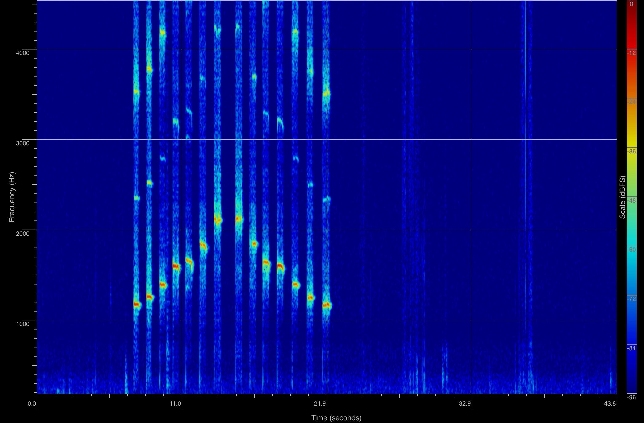
The forged cymbals diverged in diameter size from the originals by up to 1mm. This small difference in dimensions between the originals and replicas will affect the decibel levels to some degree. There are noticeable differences in loudness between the smallest replica cymbals (UC35797) and the largest ones, with a diameter 7mm larger, but a discrepancy of 1mm will have much less effect. The forging process may also have introduced variance in pitch between originals and replicas (original pitches could not be recorded because of museum handling rules). The finished replicas of UC35797, for example, produced notes a semitone apart when struck at one individual point with a stick (see Table 1), although the same size blanks were used. When clashed together, however (their most likely mode of use to judge from visual sources, see Figure 18), multiple points on the edges of the cymbals make contact with each other, producing multiple frequencies (see Figure 20). Thus we can envisage they were not intended to produce a single dominant frequency. Small pitch variations evident when each object is individually struck are therefore not significant.
The ceramic objects will be the least accurate in both frequency range and decibel levels, since the firing process affects the size of the objects, and we have little information about wall thickness, and none on the number of pellets that would have been included inside each rattle. To address the latter problem, a number of replicas were made for each original, with different numbers of pellets inside. For the bird rattle, that chosen for use in sound recording was the replica closest in weight to the original (see Table 2). For the pointed rattle, the original was intact and made a noise when moved during inspection, so this sound was recorded, and then the closest match in sound was selected from the replica rattles, even though this rattle had a greater discrepancy in weight with the original compared to some of the other versions. Despite the possible variance introduced by shrinkage during firing (compensated for by enlarging the original 3D models), the size ranges of the objects are very close to the originals. Wall thickness for all three rattles was based on that of the nut-shaped rattle, where the original was broken and thus could be measured, so this rattle replica will be most accurate in terms of decibel levels. The wall thickness of the original bird rattle looked similar to this from inspection of the hole underneath, although wall thickness might vary elsewhere on the object. Since each rattle is clearly distinguishable by size (see Table 2 and Figures 3a/3b, Figure 4a/4b and Figure 5a/5b), we can envisage that the relative loudness of the instruments as compared to each other will be the same, although the accuracy in the decibel levels may vary. Rattles simultaneously produce a range of frequencies that the human ear cannot distinguish from each other, so differences in frequency range will not be especially significant. It is also worth making the point that ancient objects like this, probably not intended for music performance (unlike our other instruments such as the panpipes) will have had a good deal of variance from one another, and even if we have not matched the decibel levels and frequency ranges of our original rattles exactly, it is likely that some Roman rattles once existed with the same qualities as the ones we have produced.
The different materials that our replicas are made from compared to the originals will not affect the decibel levels and pitches (frequencies) produced, but they will affect tone quality. Tone quality can only be subjectively assessed in any case, and so has not formed a part of the strictly experimental investigation, but it does of course affect our perceptions of the sounds in the recordings of the objects (discussed further below) and so it is worth considering briefly. How much difference in tone quality would be evident between clappers made of different types of wood, ceramic objects made in similar earthenware fabrics but with slightly different recipes, or different brass alloys, is debateable. Differences in materials are more marked for the cast metal bells between original and replica, but here we have been able to choose an alloy with similar acoustic properties to three of the bells replicated. The object that is most different from the original in terms of materials is the panpipes. Although replicas were made in organic materials, since the 3D prints in plastic best preserved the exact dimensions of the object, one of these, a PLA print, was used for the decibel and frequency measurements and the sound recordings (the most accurate is the photopolymer print, but unfortunately this was not available at time of recording). How close is the sound quality of this 3D print to a reed original? Scholars of acoustics take the view that different materials cause minimal differences in sound quality for wind instruments, as the vibrating air column is the most important part for producing the sound (Campbell and Greated 1987, 295, 404–7). To evaluate this for PLA compared to organic plant material, we 3D scanned and printed a modern whistle made from a plant stem (of unknown type) and compared the sound produced by the whistle and the 3D print replica. We could not audibly distinguish any differences between them. Similarly, the replicas in bamboo made of the PLA pipes sounded virtually the same, perhaps slightly more breathy in tone although this may be a subjective judgement. A project that created a replica of a 16th-century recorder through 3D scanning and printing also found that a professional musician could produce a tone quality from a PLA replica the same as that of the wooden original (Witkowski 2017).
Once the process of replica creation had been completed, sound measurements of the decibel and frequency levels were made and used in an evaluation of the likely social function of the objects. Since this article focuses on the replica creation process, it is not the place for a detailed discussion of the social interpretation of the sounds made by the objects, but we can give a specific example to illustrate the usefulness of the information. Measurements of decibel levels, for instance, confirmed that some instruments such as the clappers, cymbals and panpipes, could have been heard by a wide audience when used outdoors and so would be suitable for public music performances (as indeed is suggested by textual and visual evidence) while others, such as the nut-shaped rattle and bells on bracelets, were very quiet and so are likely to have been for personal use in the domestic context only (see Swift et al. forthcoming for full details).
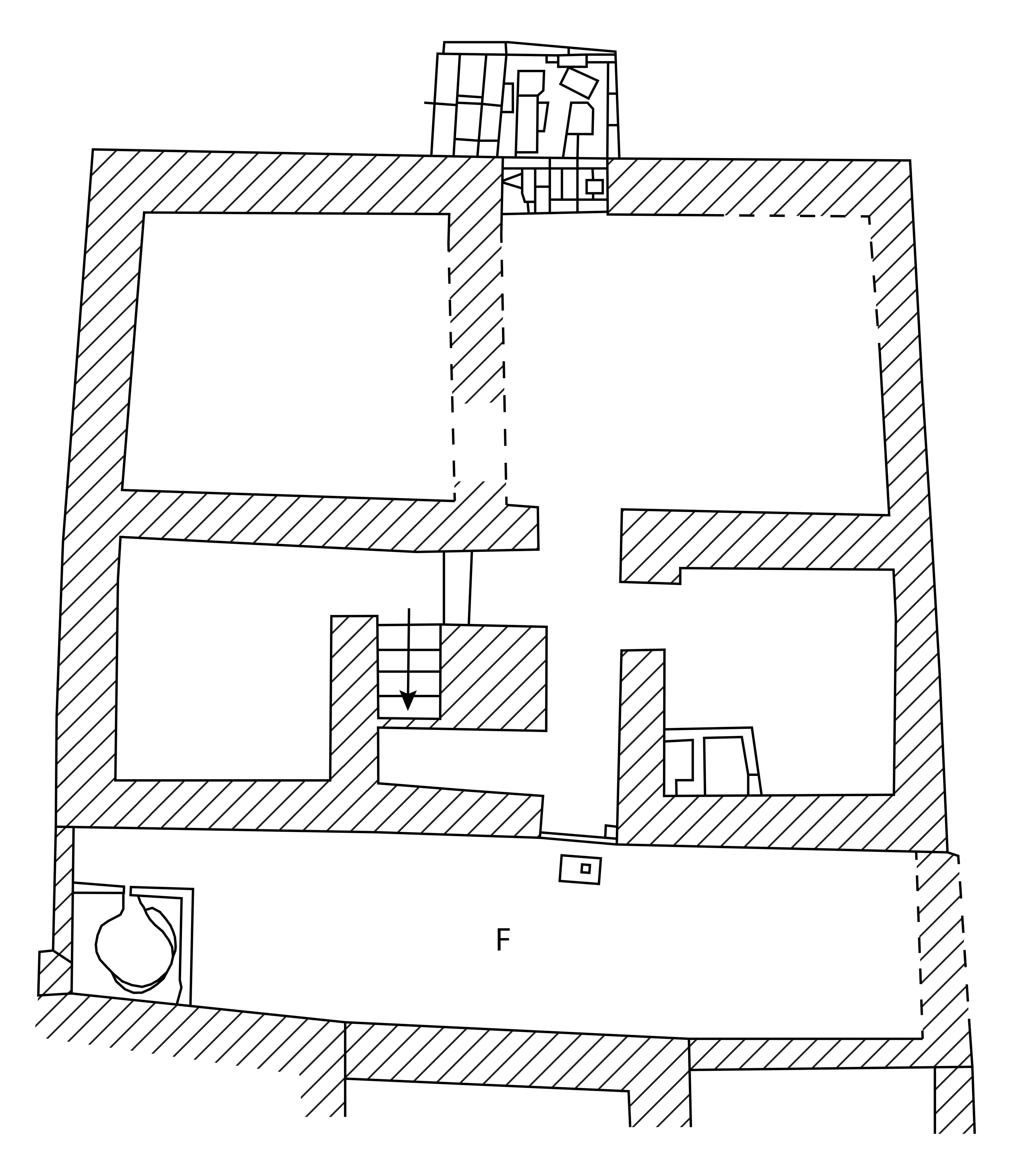
Sound recordings of the objects were made in a professional quality sound studio at the University of Kent by sound technician Frank Walker. The acoustics were modelled virtually, using the dimensions of a courtyard (approximately 2.5 × 11.8m) from a Romano-Egyptian house at Tebtynis (Figure 25), House 3200-III Room F (Hadji-Minaglou 2007, 117–26 and fig. 56). This was chosen as a typical domestic setting in which the instruments are likely to have been used (see Swift et al. forthcoming). The music performers were myself, the other project team members April Pudsey and Jo Stoner, and volunteers Ada Nifosi and David Walsh. Levels of musical knowledge varied from none at all, to ability to read music and some experience in playing and singing in amateur performances. We deliberately chose not to involve professionally trained musicians or music students, since we wanted to record the sound of instruments as played in everyday circumstances, which would have included amateur performers.
Recordings were made using two microphones set at different distances from the player of the instrument so that two recordings, one at close range and one at a mid-range distance, could be made simultaneously. Most of the instruments were deliberately agitated in order to produce their typical noise. The decibel range for each one was also recorded, by playing from as softly to as loudly as possible. The cymbals produced different noises according to how they were struck and/or held and so a range of recordings were made to capture the various possibilities. For those instruments where other uses were likely, these were also recorded, namely, the passive sound that the bells on bracelets attached to the wrist would make on movement, and the sound of the rattles when rolled on the floor as well as when shaken deliberately. Representative recordings are available in Appendix 2.
A selection of the artefacts (the wooden clappers and cymbals, the bird rattle, and the panpipes) were recorded playing specific tunes or phrases and rhythms, which were selected from scholarly publications with transcriptions of ancient music in modern musical notation (Pöhlmann 1970; Pöhlmann and West 2001; West 1992). Two sets of panpipes were tuned to different scales to reflect the variation available from this object: in addition to the diatonic scale described above used for the first set (D E♭ F G A♭ B♭ C), a further diatonic tuning was used for the second set (D E F# G A B C). Berlin Papyrus 6870 line 13 (Pöhlmann 1970, cat. no. 31; Pöhlmann and West 2001, cat. no. 51) was chosen as a tune playable by the first set, and one of the tunes from Bellermann's Anonymous (Pöhlmann 1970, cat. no. 12; Pöhlmann and West 2001, cat. no. 37) playable by the second set; both are from the Roman period. Rhythm patterns were selected from West 1992, table 5.1, choosing those within a chronological range that included the Roman period. For the cymbals and clappers, instruments which, from visual sources, we can suggest were often used by dancers (Hickmann 1949b, 523–30; Musée d'archéologie méditerranée Marseille 1997, 238), we used five-beat rhythms that were popular for dancing (West 1992, 140–43). A different rhythm also used in the Roman period was chosen for the bird rattle, an Ionic rhythm, with three beats in the bar (West 1992, 145–7), to introduce some variety (the loudness of this rattle suggests that, unlike the other rattles, it could be suitable for music performance). Recordings were also made of two percussion instruments (a set of clappers, and cymbals on handles) accompanying firstly the panpipes tune for the first set of pipes, and secondly a Roman-period song, the 'Song of Seikilos' for which the words and music are both extant (Pöhlmann 1970, cat. no. 18; Pöhlmann and West 2001, cat. no. 23). Visual sources confirm that cymbals on handles were sometimes used to accompany panpipes (Hickmann 1949b, 474; for a specific example, see the Carthage banquet mosaic, Dunbabin 2003, fig. 46). Finally, all the sound recording participants selected one or more instruments to play together freely when processing past the microphone, in order to mimic the sound of a procession passing by.
Sound recordings and replicas were also used for public engagement purposes in a temporary exhibition at the Petrie Museum of Egyptian Archaeology, UCL. A selection of the less valuable replicas and 3D prints were made available throughout the exhibition (3D prints of panpipes and clappers, and craft replicas of ceramic rattles, panpipes and clappers), with handling of the other replicas, mostly the metal ones, available at four workshops for the general public. Activity sheets were available in the museum with guidance on how to play the instruments (for instance manipulating them in different ways to produce different sounds), and examples of tunes and rhythms that visitors could try out. These were also used in the public workshops.
3D models of some objects, that could be viewed and rotated by visitors, were also included in the exhibition, together with sound recordings (as described above; see also Appendix 2) to give visitors a further idea of the sounds produced by the objects, the kinds of ensembles in which they might be played, and examples of authentic tunes and rhythms. Each sound clip could be accessed by clicking on a picture of the relevant instrument on a computer screen. After the image had been selected, the sound, delivered through headphones, was preceded by a few lines of text on the screen setting out an imaginative scenario, to encourage the listener to consider the sound in the context of everyday life in the ancient world. For example, the sound clip of the panpipes playing the tune from Bellermann's Anonymous (see above), which is one of a set of Roman instrumental exercises for learners, was preceded by the text 'Sarapion, a young boy, is learning to play the panpipes. Listen as he practices in the courtyard'. Research findings from the experimental archaeology undertaken using the replicas were also incorporated into the text panels for the display cases in the exhibition, for instance information about how quiet some of the objects were.
A total of 115 visitors filled in a visitor questionnaire about their experience of the exhibition and its associated activities (see Appendix 3 for the blank form). The completed questionnaires covered a broad spectrum of ages, with similar numbers across the different age categories (Figure 26); 38% of the respondents were in higher education. No particular trends were evident in the data for the individual age categories, and so it was examined as a single dataset.
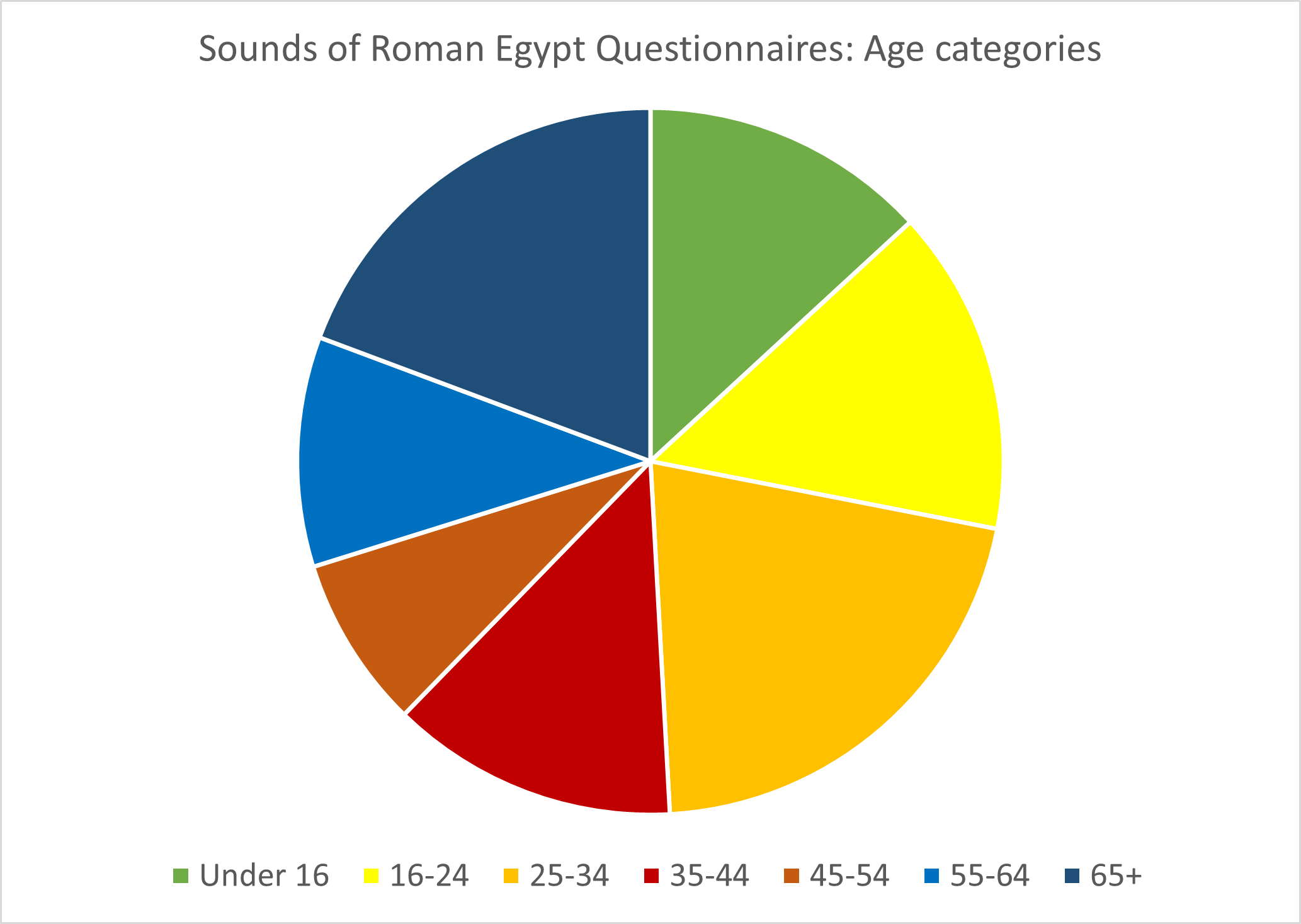
The sensory experience of the sound, and how this helped to bring the past to life, and make it more relatable for visitors, was the strongest theme of the feedback (see Table 6). Western culture is a predominantly visual one, and because museum visitors cannot usually handle original artefacts in museums, their experience of ancient objects is also primarily visual. Using objects that were both audible and tactile, and listening to sound recordings, facilitated a more immediate experience, in which people felt more connected to the past, and were consequently better able to imagine people using the original objects within a living social environment ('they seem more realistic as humans [rather] than just history').
| Visitor comments on how the sensory experience helped to bring the past to life, from the 'What you liked – tell us more' and 'How your views of Ancient Egypt changed – tell us more' sections of the Petrie Museum Sounds of Roman Egypt Questionnaire (each row is a comment from one questionnaire) |
|---|
| Having the atmosphere |
| Gives a sensory experience |
| I enjoyed the atmosphere and hearing the sounds |
| Sensuousness of sound really helped bring alive the experience |
| Bringing the soundscape...being brought a sensory experience which people of [the] past would have experienced |
| It was wonderful to get a chance to hear what the ancient instruments would have sounded like - so evocative! |
| The authentic sounds bring us together with the original culture |
| It's a more visceral experience than just reading and looking at objects you can't touch, stays in your memory for longer |
| Sensory experience – gives ideas of sounds |
| Having recordings and manipulating replicas makes the objects seem more real |
| It's good to be able to know the ancient sounds of different objects as text is always hard to imagine |
| Museums are always about the object as it is now. You rarely get to hear them |
| Because you can use interesting artefacts used by Egyptians, which felt like the real thing |
| Makes it more approachable and less ancient |
| Listening to their music changes completely my distance/perspective to the ancient world |
| Ability to imagine life back in Roman Egypt |
| More complete view of the past |
| It helps to envision Roman/Egyptian daily life |
| Brings more authenticity to historical items |
| Jollier, noisier |
| The interactivity and playing the instruments brought it to life |
| Richer – more human – it really helped |
| More alive, related |
| Brought it to life |
| Made it come alive more |
| Now it's 3D, alive |
| Ancient Egypt is now livelier |
| Makes it come to life (the music) |
| They seem more realistic as humans [rather] than just history |
We asked visitors to indicate what they liked best about the exhibition in a multiple choice question (Figure 27). Was it seeing the original objects, trying out the replicas, hearing the sounds, or playing with the 3D models of the instruments? Most found it difficult to choose, with more than half choosing multiple aspects. The most popular individual choice, of about a quarter of respondents, was hearing the sounds. Those who liked multiple aspects also mentioned the sounds more often than the other elements. Although trying out the replica instruments was selected as the individual favourite by comparatively few (6 respondents), the sound recordings also depended on the existence of the replicas, and so we can conclude that the artefact replicas were fundamental to the popularity and success of the exhibition. In the section 'Tell us more about what you liked', multiple respondents also mentioned hearing or experiencing the sounds (14), enjoyment and/or fun (8), and the opportunity to see the original artefacts (6). From the multiple choice question, a combination of seeing the original artefacts and hearing the sounds produced by the replicas was popular (13 respondents), showing that the replicas and 3D models were not seen as a substitute for viewing the originals, but rather, as a supplement that enhanced visitor experience of the original artefacts.
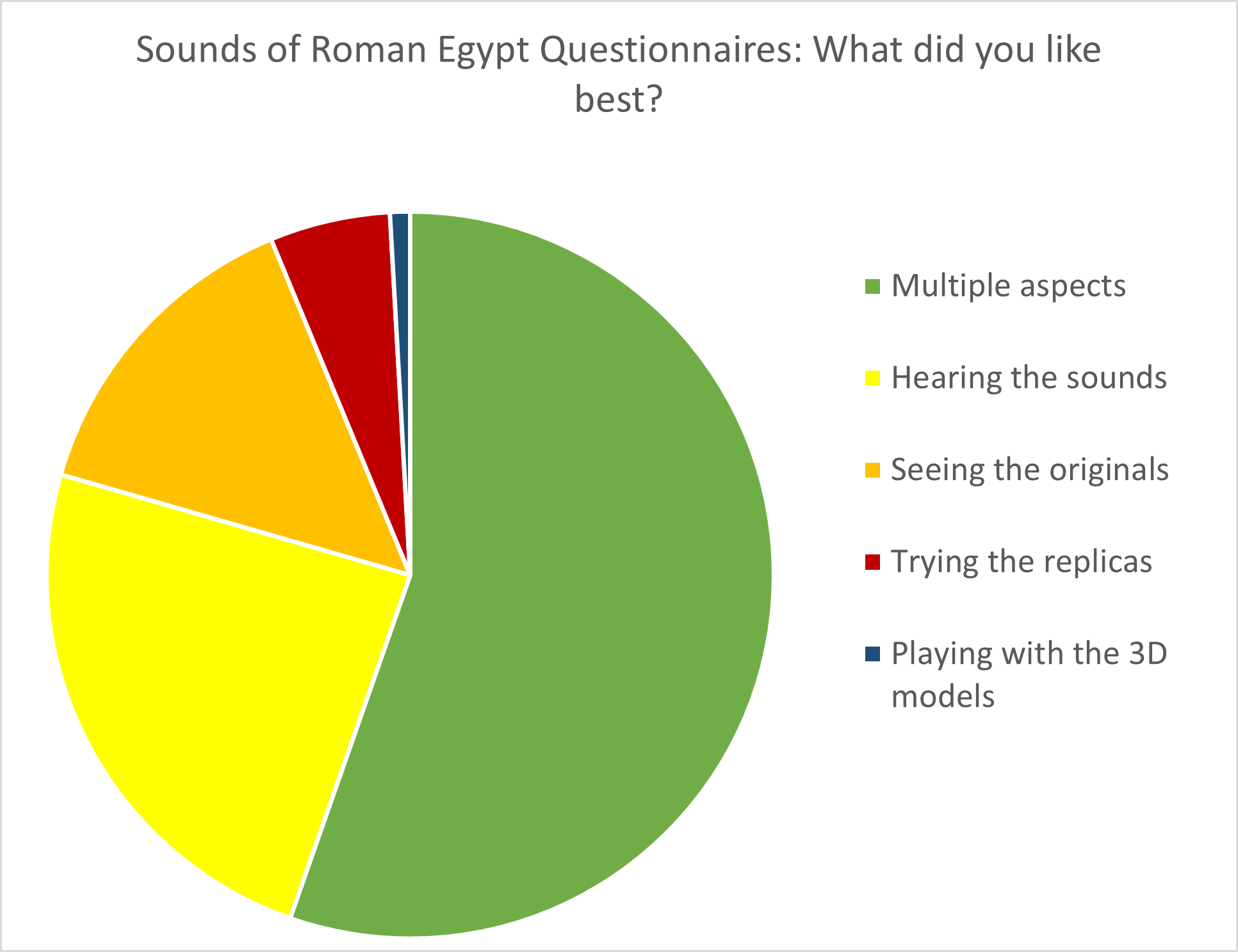
In response to the question 'What did you learn that was new?', 56% of respondents said that they learned something new about music, sounds, or instruments. They reported learning what instruments were played, and how to play them. They said they had learned what instruments sounded like and how loud or soft they were. These aspects were all directly communicated by the artefact replicas, and the sound recordings made using the replicas. Also mentioned were rhythms, musical notation, soundscapes, how the instruments were made, and how music contributed to everyday life.
Another common theme was how the exhibition had broadened people's conception of Egypt. Sixty-two per cent of visitors said that it had changed their view of Ancient Egypt. Some did not have much or any awareness of the Roman period ('I hadn't thought about Romans being in Egypt'; 'previously I had little sense of a Roman culture in Egypt'). For others, who had a popular image of Egypt as being mostly about things like burials and hieroglyphs, it broadened their conception to include aspects of everyday life ( 'Oftentimes we hear of Egypt in terms of elaborate tombs, and this showed the life of the everyday'; 'Nice to listen to Egyptian sounds rather than just funeral objects/graves'). Many people had not previously thought about music and sound in the ancient world at all (mentioned in 7 responses), demonstrating the value of the exhibition in transforming wider perceptions of the past.
To summarise, the processes of 3D scanning, 3D model creation, 3D printing, and craft reconstruction described above can be used to create a set of replica objects that can be described as 'functional replicas' – that is, they replicate with reasonable veracity, greater for some objects than others, the features of the objects under investigation. They can be used for both research and public engagement activities. From a research perspective, the accurate re-creation of decibel levels and pitches for some objects and, less precisely, their approximate timbre, has facilitated an enhanced understanding of the likely social context of use and audibility to users within a wider acoustic environment of a range of sound-making objects. Visitor feedback from the use of the artefact replicas in the 'Sounds of Roman Egypt' exhibition at the UCL Petrie Museum makes clear their strong contribution to visitor experience, particularly with regard to creating a sense of immediacy for visitors that helped to bring the past to life. We have also been able to evaluate to a certain extent how far the necessary compromises described above have affected the sounds produced by the objects since in a few cases we have both original and replica sounds to compare with each other. Small variations in measurements were found to significantly affect pitch, and so this will be exact in replica creation only where no variation has been introduced in the manufacturing process. 3D scan data and sound recordings have also been made available for future use in both research and public engagement. Finally the re-creation of a plausible acoustic environment, the courtyard of a Romano-Egyptian house of a type in which many of the instruments are likely to have been played, provides an insight into the acoustics of the space and its effect on the sounds of the instruments, and enables us to consider wider aspects of the experience of soundscapes in Roman Egypt.
The project for which this is one of the published outputs, Roman and Late Antique Artefacts from Egypt: Understanding Society and Culture, was funded by an AHRC project grant, and we are very grateful to the AHRC for this support. Thanks also to current and former staff at the Petrie Museum of Egyptian Archaeology, especially Louise Bascombe, Anna Garnett, Maria Ragan, Alice Stevenson, and Alice Williams, and to the Petrie Museum and the British Museum for permissions to reproduce images of objects in their collection. David Walsh and Ada Nifosi kindly assisted by playing some instruments for sound recording, and Egert Pöhlmann by allowing us to use his transcripts of music in the recordings. Eric Hall, formerly a professional potter, kindly provided advice about the replica creation for the ceramic artefacts, and Prof. Kevin Dawe, University of Kent, and Andrew Lamb of the Oxford Bate Collection, assisted with information about comparative ethnographic musical instruments; Keith Greenhow, Daniel Knox and Julien Soosaipillai (all University of Kent) made the replicas of the wooden clappers (other replicas were made by the technicians and craft practitioners credited above). Many thanks to all of them.
Internet Archaeology is an open access journal based in the Department of Archaeology, University of York. Except where otherwise noted, content from this work may be used under the terms of the Creative Commons Attribution 3.0 (CC BY) Unported licence, which permits unrestricted use, distribution, and reproduction in any medium, provided that attribution to the author(s), the title of the work, the Internet Archaeology journal and the relevant URL/DOI are given.
Terms and Conditions | Legal Statements | Privacy Policy | Cookies Policy | Citing Internet Archaeology
Internet Archaeology content is preserved for the long term with the Archaeology Data Service. Help sustain and support open access publication by donating to our Open Access Archaeology Fund.
 Home
Home