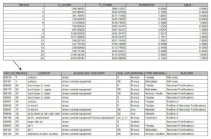
Figure 3: Provenance and artefact data tables for Vetera I, showing unique identifier codes (i.e. trench numbers) in both tables and XY coordinates added from GIS map.
Because the original plans, and therefore the digital plans, were not truly geo-referenced, the next step in the procedure was to create an XY coordinate system for each site that was internally consistent for that site, but not necessarily connected to a global coordinate system. To be able to plot data from the artefact catalogues onto the GIS map both sets of data needed the 'common key' that referred to a unique position on the map. This 'common key' was compiled from the published provenance registers for each site and from provenance information in the artefact catalogues. It needed to be exactly the same in the GIS map as in the digitised artefact catalogue.
As is evident from the above discussion, the level of detail provided for each provenance, in the site publications, varies considerably within and between the sites. At times the provenance information refers only in general terms to an excavation trench or building/area within the site, including an area or trench that may cover more than one building. At others information is provided on more specific locations within these areas, such as a particular room. And sometimes finds may be provenanced to specific and identifiable features, such as clearly defined and stratified features (e.g. pits). These variations in levels of detail had to be taken into account when setting up the coordinate systems for each site. And because of this variation, XY coordinate systems, rather than polygons representing specific areas of the fort (e.g. buildings or rooms), were used.
The published plan of the excavation trenches at Vetera I had a general set of coordinates that were listed in the trench provenance register (Hanel 1995, 341-52 and plan 1). However, the coordinate grid in this plan was not precise enough for the objectives of this study, especially for the more specific provenance information provided in the artefact catalogue (e.g. artefact provenances to pottery kilns or pits) and in the more detailed trench plans (i.e. Hanel 1995, plans 2-12). Therefore, a new set of XY coordinates was generated from the GIS map using a GIS script supplied by ESRI (addxycoo.ave). The application of this script generated an XY coordinate at the mid-point of each feature in the plan (e.g. the trench). However, on this occasion, this first required that each trench, or feature, was drawn as a closed shape, or polygon. These closed polygons ensured that the non-geo-referenced, but fixed, system of coordinates could be securely attached to these locations within the digitised site plan. As each uniquely identified location now had its own XY coordinates, an attribute table could be generated in ArcGIS using the unique location identifiers and the XY coordinates encoded in the shapefiles. This attribute table, with fields for the X and Y coordinates for all the numeric identifiers, could then be exported into the artefact catalogue Excel spreadsheet as a separate table of provenance data. The XY coordinates of each unique identifier could then be linked to the artefact data by querying the database.
The printed site plan for the fort at Ellingen had a more precise grid coordinate system than the plans for Vetera I (Zanier 1992, plan 1). These coordinates are included in the provenance register (Zanier 1992, 320-32) and could be incorporated in the GIS map. While the plan for Ellingen includes a site grid, this was an open-plan excavation. So, no trenches are identifiable in this plan, for which the XY coordinate of the mid-point could be generated using the script, as was the process for Vetera I. A new system for registering spatial information was required; one that would recognise and incorporate the spatial information from the provenance register. The coordinates on the printed site plan needed to correspond to the unregistered and 'floating' XY coordinates that are built into the ArcGIS program. The simplest method was to drag and re-scale the digitised site plan so that the 0-0 XY coordinate point on the plan of Ellingen was now located directly over the 0-0 point in the ArcGIS program. Once the 0-0 point was in place, the site could be re-scaled so that each 10 metre unit on the grid corresponded to the measurement of 10 metres from the ArcGIS 0-0 point, and so on. All of the features digitised onto the plan could now be spatially registered to the 0-0 point. This procedure also necessitated the editing of the projection in ArcGIS so that the units of measurement were now simply registered in metres, rather than, for example, in feet or degrees. The process for producing a coordinate system for Ellingen's artefact catalogue and digitised site map essentially meant that ArcGIS converted the numeric grid of the original plan to produce a set of pseudo-latitudinal and -longitudinal readings. These readings correlated with the coordinates in the published provenance register (Zanier 1992, 320-32) and in each entry in the artefact catalogue. A summary provenance table was generated by importing the printed provenance register into a worksheet in the spreadsheet for the artefact catalogue.
In the provenance register each location entry included a provenance code or unique numeric identifier; a location description according to the building, part of a building or feature; and, generally, a set of grid coordinates corresponding to those in the printed site plan. Those entries in the provenance register without coordinates were either generalised areas or referred to stray finds from the fort or vicus. The latter were often from earlier excavations and chance finds. Some numeric location identifiers in the provenance register were assigned a range of coordinates; and sometimes two numeric identifiers had the same set of XY coordinates, often because these identifiers referred to the same location but to different building phases. For those locations without coordinates, appropriate coordinates had to be compiled manually from the description of the location, or from its mid-point (e.g. the mid-point of the east part of Building C). A mid-point also had to be used where the numeric identifier had a range of coordinates in the provenance register. Stray finds, without coordinates but with a provenance code and a general location (e.g. the vicus, the north gate area, etc.), were assigned appropriate coordinates. Artefact inventory numbers were based on these provenance codes but not every catalogue entry had such an inventory number. Such cases were provided with a set of XY coordinates that plotted them together, as stray finds, outside the fort precinct in the bottom right corner of the final GIS map. Thus, further unique codes, each with an XY coordinate, were added to the provenance data table in the artefact catalogue spreadsheet, so that each actual location had a unique identifier code and each artefact in the catalogue could be plotted.
No coordinate system was available for the printed plans of the fort at Oberstimm. The artefacts from Schönberger's excavations are provenanced to excavation areas or to specific features within these areas. Artefacts from the earlier excavations (e.g. Witz 1911) were provenanced to buildings. Thus, the location descriptions in Schönberger's provenance register (Schönberger 1978, 314-18) and in the artefact catalogues for this site are published in varying levels of detail, relating either to entire open excavation areas, to buildings, to particular features within these areas, or to stratified contexts. The process used for adding a coordinate system to these data was a combination of those used for Vetera I and for Ellingen. As for Ellingen, a provenance data table was compiled from the provenance register. As for Vetera I, each excavated area or feature was given a unique identifier code, but these had to be compiled manually. For example, posthole 20 in excavation area 1a was given the code 1:010200, and this unique identifier code was manually added to the relevant entry in the provenance data table.
These codes were then added to the attributes table in the GIS map, by creating a new field for artefact provenances within this table and then manually inputting the relevant code for each required location (e.g. for a pit or for general location within the trench) into the new field. The XY coordinates thus generated for each identifier code were then exported back into the provenance data table.
For the fort at Hesselbach, the published plans and the provenance register (Baatz 1973, 113-14) were in a similar format to those for Oberstimm, and most artefacts were provenanced to a building or part thereof. However, there were only forty-five identifiable locations in the provenance register for Hesselbach so the easiest way to bring this information into the provenance data table was to take manual readings of the locations from the GIS map and paste these readings directly into the provenance table.
This manual procedure was also used for Forts I and II at Rottweil, which had only fifty-five identifiable excavation areas and features, by which the artefact catalogue was organised in the publication, with the artefacts usually provenanced to specific features within an excavation area. Some of these provenances were precise, such as pits and wall trenches, some were particular buildings and building phases, but some comprised a general excavation area. The excavation areas usually included not more than two buildings or comparable feature (e.g. a street).
Figure 3: Provenance and artefact data tables for Vetera I, showing unique identifier codes (i.e. trench numbers) in both tables and XY coordinates added from GIS map.
By this process, which varied slightly for each site, the XY coordinates for each provenance code could be generated where required (e.g. where codes were not originally assigned in the published documents) for each individual artefact from each site (Figure 3). The XY coordinates themselves were not added directly to each individual artefact or digitised catalogue entry, however. Instead, these coordinates were included in a separate table of the summary data for each provenance - the provenance data table. Although each site required different methods to generate XY coordinates and provenance codes, once these were defined, the procedures were the same for each of the sites. That is, the provenance data table could be linked to the artefact catalogue table through the unique identifier codes allocated to each provenance location within the plans, and so provide a set of XY coordinates for each artefact, using a select query in Access. However, the artefact catalogue tables first needed to be created.
© Internet Archaeology/Author(s)
URL: http://intarch.ac.uk/journal/issue24/6/2.1.3.html
Last updated: Mon Jun 30 2008