A number of imaging methods have been employed to assess the direction of the lines, to understand their relationship to each other, and the line order and phasing. To do this we integrated light microscopy, reflectance transformation imaging (RTI), white light 3D surface scanning, and scanning electron microscopy (SEM).
Light microscopy was used but was limited to low power light microscopy, using a stereoscope with 10x to 100x magnification. The shallowness of the engravings presented a challenge for assessing the line order, further compounded by the presence of highly reflective gold-coloured iron pyrite crystals adhering to the surface (see below), which made analysis with conventional light microscopy challenging; the fixed and direct light source making the engravings virtually invisible. This is a common problem when analysing shallow engraving on stone surfaces, thus digital methods are increasingly advocated as alternatives to or as methods to be used in tandem with microscopy (Bello et al. 2013; Fritz 1999; Fritz and Tosello 2007; Güth 2012; Tosello and Villaverde 2014).
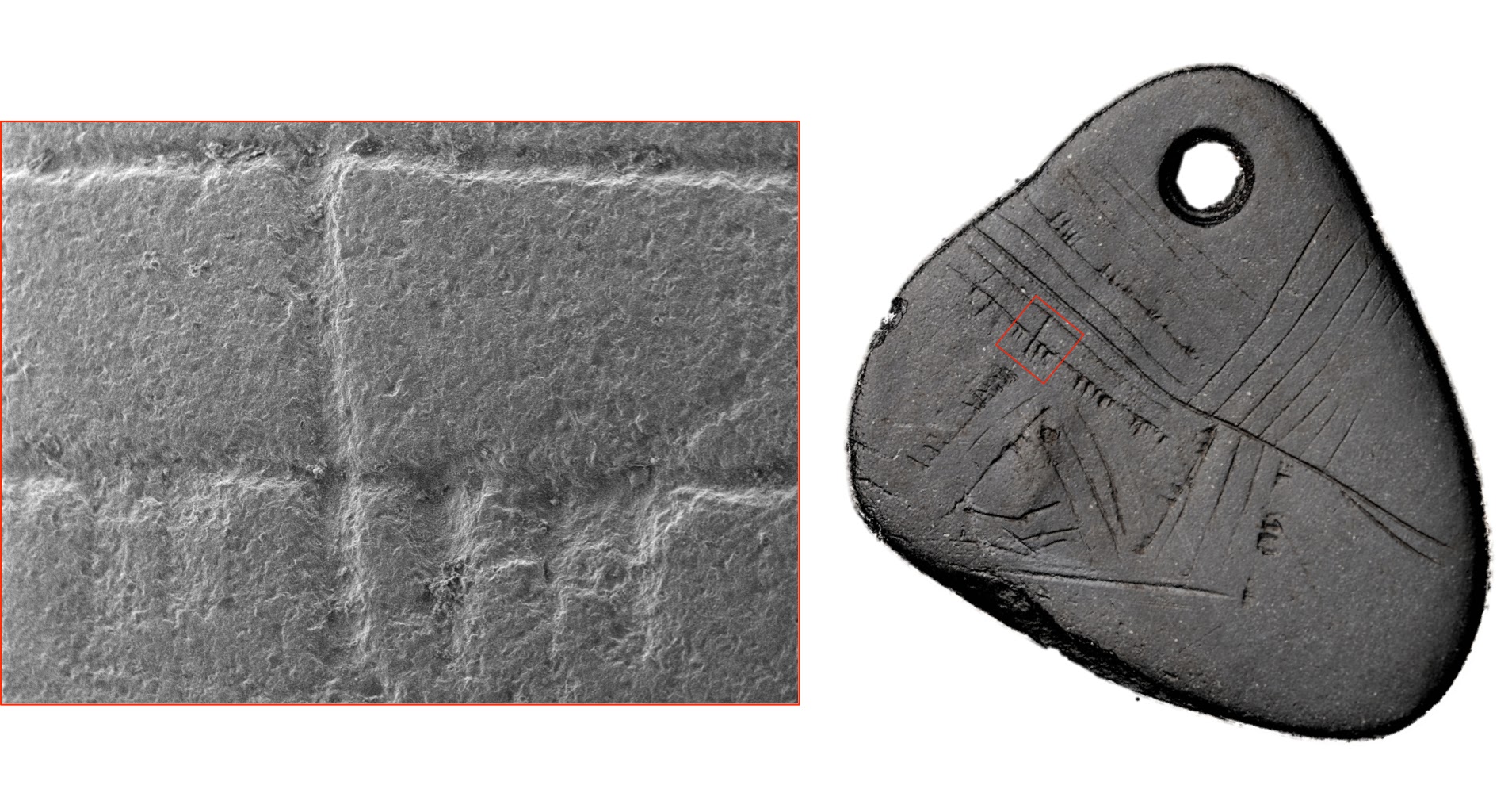
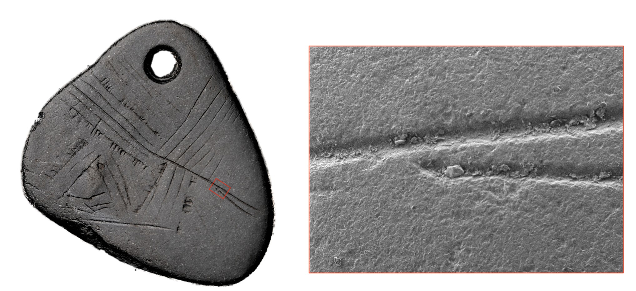
In contrast, SEM, a non-light based technique, yielded significantly better results on this surface. The reflection from the gold-coloured particles was immediately removed by the SEM, making line-order relationships far easier to recognise and analyse. A Hitachi TM3030Plus tabletop scanning electron microscope (SEM) was used to image key details of the engraved lines (Figures 9, 10 and 11). This piece of equipment was chosen over other SEM options since it is non-destructive to artefacts. No sputter-coatings (such as gold, carbon, palladium) are required for imaging using this SEM; a major advantage to traditional high vacuum SEM analysis. SEM images were collected in secondary electron mode and backscattered electron mode and from 25x to 3000x magnification.

Similarly, the composite images produced using RTI, and manipulating the light source to an oblique position within the software, provided a highly effective tool for assessing the relationships between engraved lines. RTI is a form of computational photography. A set of photographs of an object are captured from a fixed camera and in each photograph the object is lit from a different direction. Using software called RTI builder, these photographs are then combined in order to generate an interactive image within which the user can control the direction and power of the light. RTI works by calculating the surface of an object based upon the appearance of each pixel when lit from multiple light positions. Each pixel is assigned a direction and an angle of slope based upon its appearance within the original photographic dataset. Using the resulting surface model it is possible to apply visualisation algorithms to enhance surface characteristics (Malzbender et al. 2004).
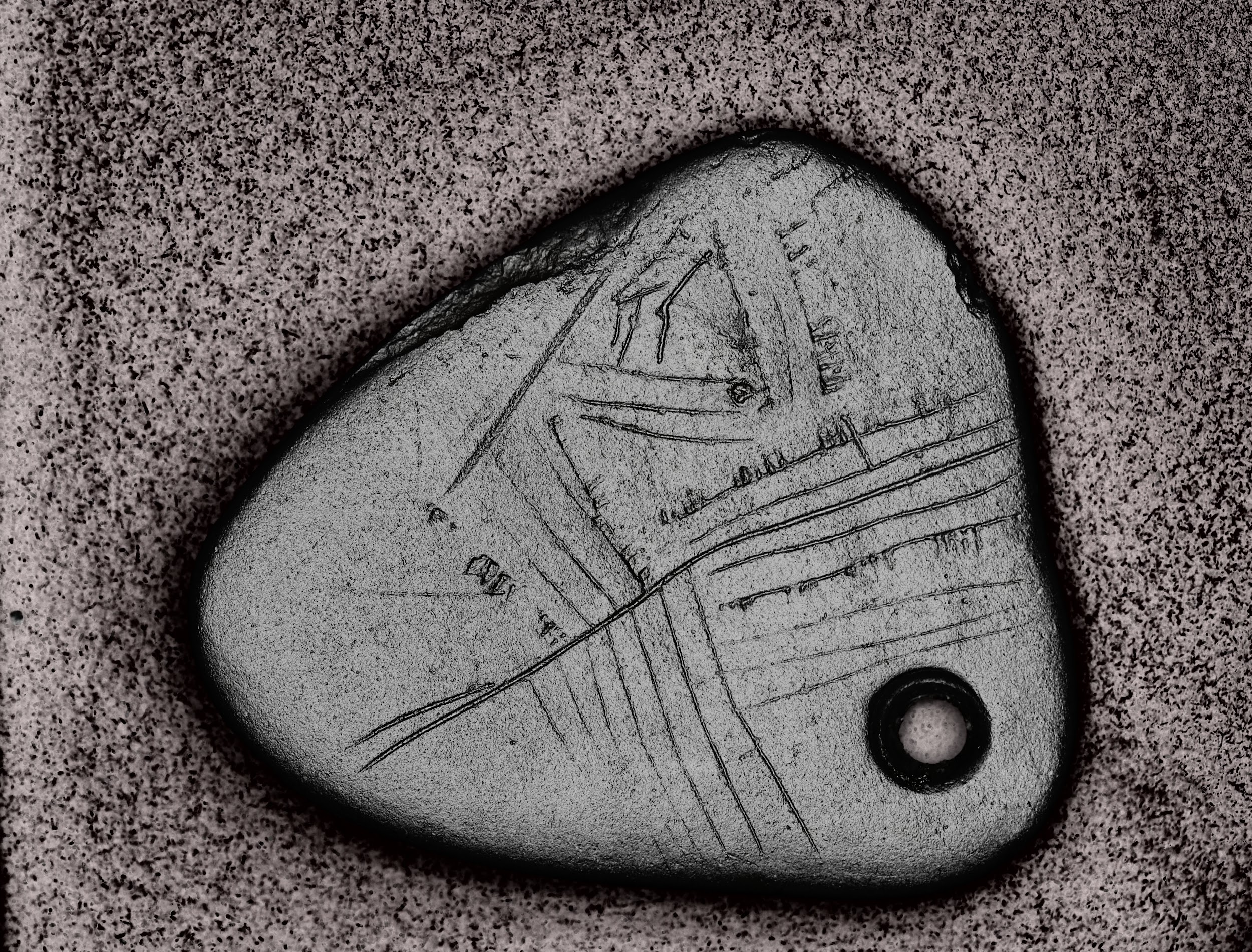
RTI has the capacity to reveal complex surface details such as small incisions or wear marks (Riris and Corteletti 2015) and has been used extensively in the detailed examination of archaeological material (Earl et al. 2011; Jones et al. 2015; Newman 2015), including finds from Star Carr (Duffy 2013). In this instance, the method has helped to enhance the incised surface details on the pendant and the sequence of incisions is made much clearer through the enhancement of specific details at the intersection of lines (Figure 12). RTI has also been useful in helping to develop an overall impression of the patterning through the production of images using specular enhancement (Figure 13). Specular enhancement allows the user to alter the appearance of the captured object by suppressing the colour of the surface and making it more reflective. Using this technique it becomes possible to observe underlying topological characteristics without colour information. This was very useful in observing incisions on the surface of the shale pendant that were unclear from the original photographs.
The light-based microscope was used to support a line-order analysis primarily established through these digital methods, being used to cross-check results against the pendant's unmodified surface. The use of these varying methods in tandem yielded a better understanding of what is a very fine and subtle series of engraved lines, in parts heavily modified by post-depositional action, than any single method in isolation might have allowed.
In addition, we attempted to surface scan the object in order to create a detailed 3D record, particularly in light of the fact it is very fragile and prone to lamination. White light 3D surface scanning was carried out using a Breuckmann SmartScan 3D-HE (Breuckmann GmbH, Meersburg, Torenstraβe). Both sides were scanned individually and superimposed, using common landmarks found on the edges of both scans, using the image-processing software Avizo 8.0 (Visualization Science Group Inc). The mesh was then cleaned using MeshLab v1.3.2 (Visual Computing Lab –ISTI-CNR). This produced a 3D model of the pendant, which while removing the original colour, was able to highlight surface details including some of the faint engraving and the nick on the non-engraved side (see Figure 5).