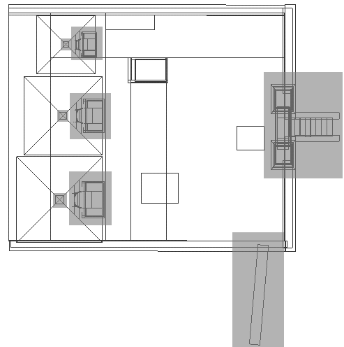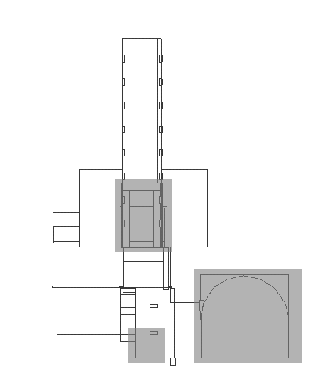
These views were created using the 'wire frame' option in CosmoWorlds that allows the model to be rendered showing the outer edges of each face only, illustrating the structure of the model. The shaded areas in the figures illustrate parts of the model for which there were no measurements given in the archaeological reports, or where those measurements conflicted with those given in the plans.
Figure 10: The completed basic wire frame model from the left.

All faces are shown here (figures 11, 12 and 13), indicating how the model was made. For example, the ends of the barrel-vaulted chamber in room B (see figure 7) is made of many triangular polygons to create a semi-circular end to the roof. The stairs on the entrance way and from room B to room D are made of a series of identical boxes. The front doorway and stairway are based on an artist's impression, although there was evidence to suggest a structure such as this had been in place. The doorways of the pyramids, too, are based on an artist's impression. The brick steps in the side of the pit differ in number and placement in the archaeological reports and the plans. The doorway into room A was destroyed by the excavations and no trace of it exists.
Figure 11: Showing the courtyard from above

The courtyard square had to be split into four large sections to accommodate the gap for the entrance to Sen-nedjem's tomb. The pyramids can be seen to be fairly complex structures because of their doorways and portals. All three pyramids are identical, merely scaled to different sizes. The front stairway and doorway are based on an artist's impression, as is the wall on the left (although there was archaeological evidence to suggest such a doorway and walls had existed). The front doorways of the pyramids are based on the artistic impression, but consistency in dimensions is maintained between all three and, again, there was some archaeological evidence to suggest this construction. The Pyramidia (on the top of the pyramids) are correct in size but would have been painted and covered in hieroglyphs. Only fragments of these were found and so they could not be reconstructed.
Figure 12: This view shows the lower portion of the model from above

The pit entrance is shown at the bottom of the illustration (the two rectangles either side are the series of brick footholds embedded into the walls down the whole depth of the pit). The first room is A, then stairs to B are shown (see figure 7). The smaller pit to room C, on the right, again shows footholds. Rooms C and A do not overlap in the model because of the large difference in height. The angle of the rooms in relation to each other was contradictory in both reports and the final plans. It is suspected that they are at more of an angle than is represented here.
Figure 13: View of the side of the barrel-vaulted inner chamber; room C

This gives a sense of how deep room C is below ground. The doorway to room A is a reconstruction, as discussed above. There was a large step at the bottom of the smaller pit; this had to be removed as the avatar could not crouch and turn to get into room C, so the inner tomb was effectively blocked. The end walls of room C are presented as two large squares separate from the rest of the chamber: this was to aid the texture mapping of the images onto the surface. From the inside they appear as part of the barrel vaulting. The barrel vault is also shown as a perfect symmetrical shape; in reality the two ends are of slightly different dimensions.
© Internet Archaeology
URL: http://intarch.ac.uk/journal/issue7/terras/plan.htm
Last updated: Mon Nov 29 1999