Figure 1: 'Section of the agger' (i.e. rampart) at 'Moel Gaer', one of the 'Castra Clwydiana', as sketched 'on the spot' by Ffoulkes (1850), stating with disarming honesty that he sought 'rather to represent the mode of construction than to give a correct likeness of the viscera of the agger'
Figure 2: Plan of 'ancient camp on Moel Fenlli' (Ffoulkes 1850). (Original published at approximately 1:6666.)
Figure 3: So-called 'detail' plan of hut-circles and rock-shelters on St David's Head (Baring-Gould et al. 1899). (Original published at 1:480.)
Figure 4: Revetment wall of inner bank of Dinorben, unearthed at Gardner's behest, not far from his Section 10 (Gardner and Savory 1964, pl. IIIb). © National Museum of Wales
Figure 5: Drawing of Section 20 at Dinorben, as prepared for publication on the instructions of Savory from field-drawings of 1914-22 by Gardner, and showing the supposed stratified context of an iron axe-head (Gardner and Savory 1964, fig. 8), with drawings of the axe at top right (Gardner and Savory 1964, fig. 24.1). (Original of section published at approximately 1:350, of axe at 1:3.) Cf. Figure 6. © National Museum of Wales
Figure 6: Inner bank of Dinorben under excavation, probably in 1922 (Section 20), showing a 'workman' standing on spoil and brandishing a pick-axe with intent (Gardner and Savory 1964, pl. XVIIb); the contentious iron axe (Figure 5) was claimed to have been found some 3m below the foot of the revetment wall seen immediately under the crest of the bank (as labelled 'B' below 'Rampart 1' in Figure 5). © National Museum of Wales
Figure 7: A stretch of the inner bank of Dinorben under excavation in 1978, looking along its line and showing paired postholes of the earliest rampart cutting into a colluvial deposit; Gardner's Section 10 was taken out more deeply in 1914, as represented by the shaded area crossing the foreground between postholes (cf. Guilbert 1979a, 184-5; 1980, 337; and see Dinorben, Figure M). Photograph G.C. Guilbert
Figure 8: Excessively narrow trenches opened in 1930-1 across the interior (left) and the rampart of Llanmelin Camp (Nash-Williams 1933, figs 6 and 15). © Cambrian Archaeological Association
Figure 9: Insensitive and partial excavation of the entrance to Llanmelin Camp in 1932 did not deter the excavator from presenting a plausible plan (Nash-Williams 1933, figs 37 and 35). (Original of plan published at approximately 1:470.) © Cambrian Archaeological Association
Figure 10: Narrow and selective wall-chasing trenches at the Isthmus Gate of Pen Dinas, Aberystwyth in 1934 (understandably leaving the excavator looking rather glum), though, much as at Llanmelin (Figure 9), it can be made to look convincing in the drawing-office (Forde et al. 1963, pl. IVb and fig. 6). (Original of plan published at approximately 1:475.) © Cambrian Archaeological Association
Figure 11: The North-West Gateway at Moel Hiraddug, as disclosed in 1954-5 (Houlder 1961, pl. VIa and fig. 6). (Original of plan published at approximately 1:390.) © Flintshire Historical Society
Figure 12: Plan of area stripped at the southern end of the Inner Camp of Ffridd Faldwyn in 1937-9, showing palimpsest of postholes for palisades/rampart and complex gateway as well as an array of four-posters and a six-poster extending into the interior (O'Neil 1942, fig. 5). (Original published at approximately 1:200.) Cf. Figure 13. © Cambrian Archaeological Association
Figure 13: Postholes of internal structures uncovered at Ffridd Faldwyn, looking south-south-west (O'Neil 1942, pl. IB). Cf. Figure 12. © Cambrian Archaeological Association
Figure 14: Plan of multiple-enclosure promontory fort at Caerau, Henllan, showing trenches and area excavated in 1942, with enlarged plan of area stripped in the lee of the inner bank, revealing several posthole-structures, including at least one roundhouse (Williams 1945, figs 2 and 4). (Originals published at approximately 1:800 and 1:135 respectively.) © Cambrian Archaeological Association
Figure 15: Plan of Castell Odo, showing trenches of 1958-9, distributed across the hillfort to sample features that were mostly identifiable before excavation (Alcock 1960, fig. 2). (Original published at approximately 1:585.) © Cambrian Archaeological Association
Figure 16: Plan of Coygan Camp, showing uneven, but locally dense and gridded, distribution of trenches excavated in 1964-5, before the hillfort was erased by quarrying (Wainwright 1967, fig. 3). (Original published at approximately 1:465.) © Cambrian Archaeological Association
Figure 17: Plan of Walesland Rath, showing palimpsest of features revealed by stripping the enclosed area in 1968, the first time this had been done to a hillfort-related enclosure in Wales (Wainwright 1971, fig. 2). (Original published at 1:365.) Cf. Figure 18. © Cambridge University Press
Figure 18: Secondary plan of Walesland Rath, with peripheral structures reinterpreted as a series of four-posters and six-posters (Williams 1988, fig. 10). (Original published at approximately 1:600.) Cf. Figure 17. © The Society of Antiquaries of London
Figure 19: Crawford's plan of Pen Dinas, Llanaber (1920), with contours at 1ft vertical interval, constructed from 1500 spot-heights read with a level. (Original published at 1:400.) Cf. Figure 20. © Cambrian Archaeological Association
Figure 20: Gresham's plan of Pen Dinas, Llanaber (1967, fig. 60), lacking contours. (Original published at approximately 1:1000.) Cf. Figure 19. © Merioneth Historical and Record Society
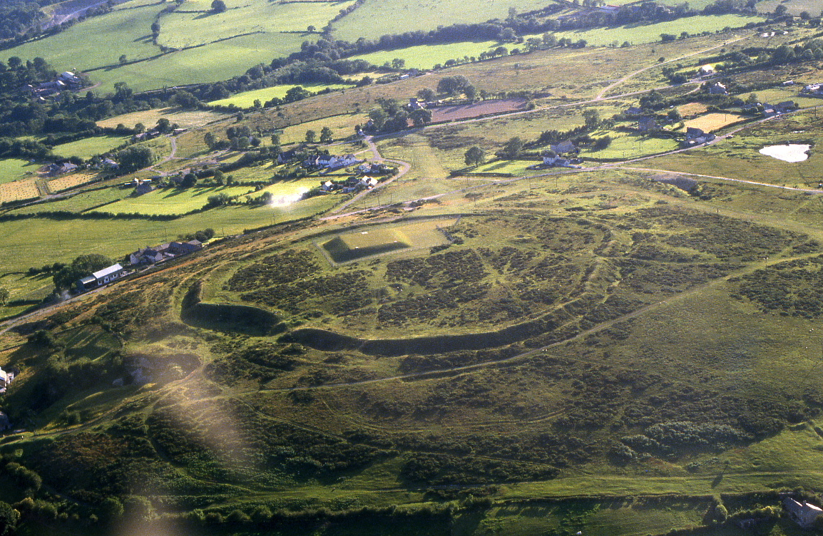
Figure A: Moel y Gaer, Rhosesmor: air-photograph looking west, taken in 1985, following construction of a covered reservoir within the area previously excavated archaeologically. Photograph C.R. Musson/Clwyd-Powys Archaeological Trust
Figure B: Moel y Gaer, Rhosesmor: sketch-plan of Phase 1 structures identified by excavation, principally post-ring roundhouses, each shown by a circle marking the inferred wall-line, broken only at the doorway or porch, but also including a circle of twelve small oval pits and a series of posthole-pairs, which may belong to this phase. At top right, one-tenth-scale sketch indicates the probable approximate course of the Phase 1 palisade-slot, with the excavated area of 1972-4 outlined
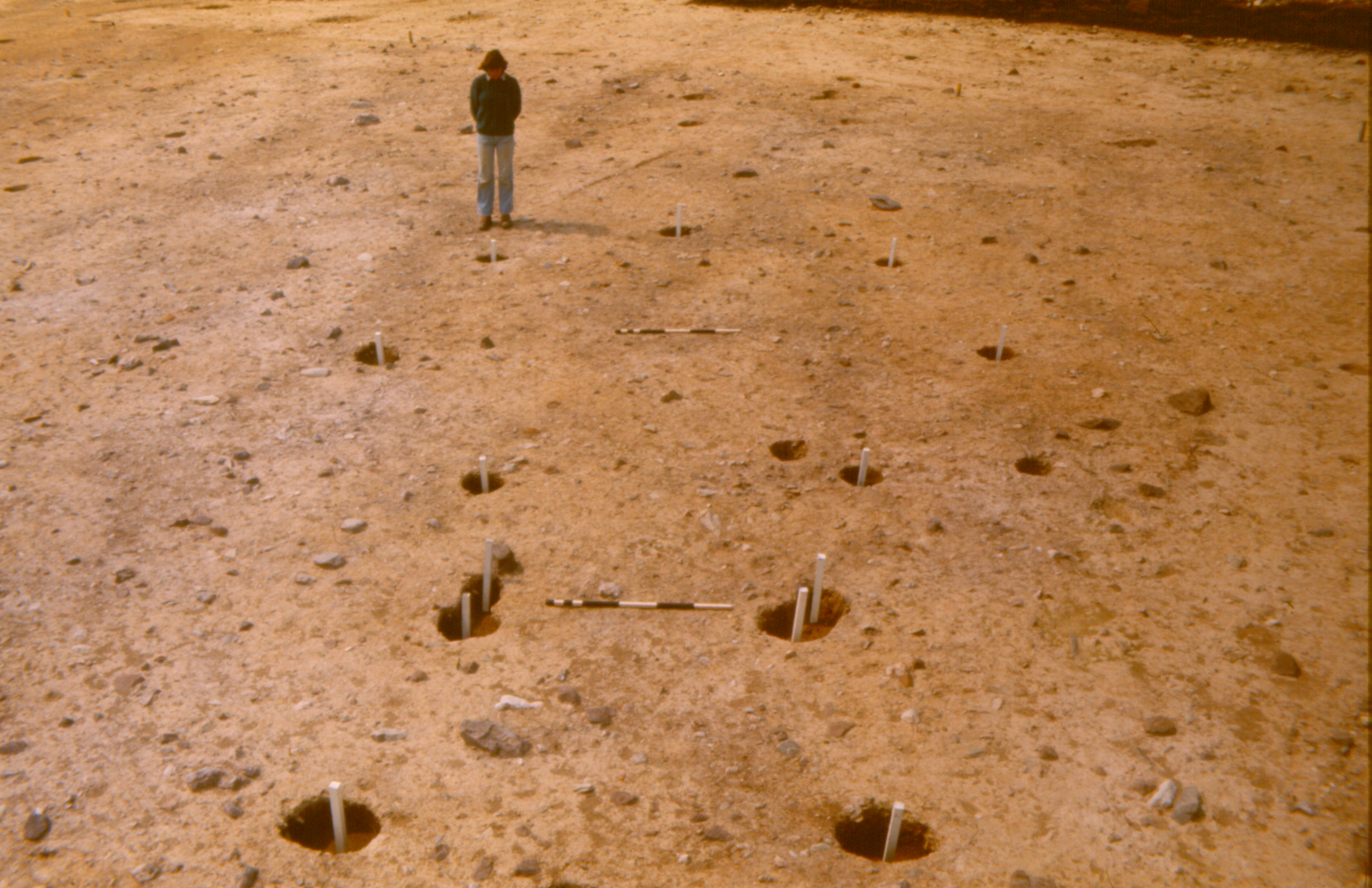
Figure C: Moel y Gaer, Rhosesmor: excavated post-ring roundhouse of Phase 1, with postholes of porch, in foreground, and those of internal ring all marked by white pegs. Photograph G.C. Guilbert
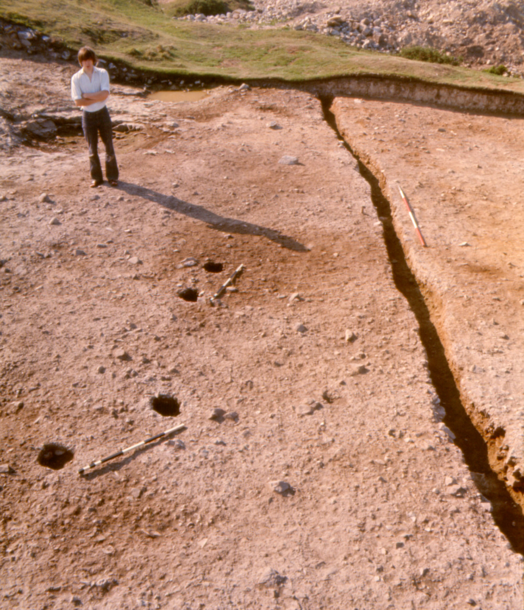
Figure D: Moel y Gaer, Rhosesmor: 12m length of Phase 1 palisade-slot together with two enigmatic posthole-pairs (marked by scales 1m long). Photograph G.C. Guilbert
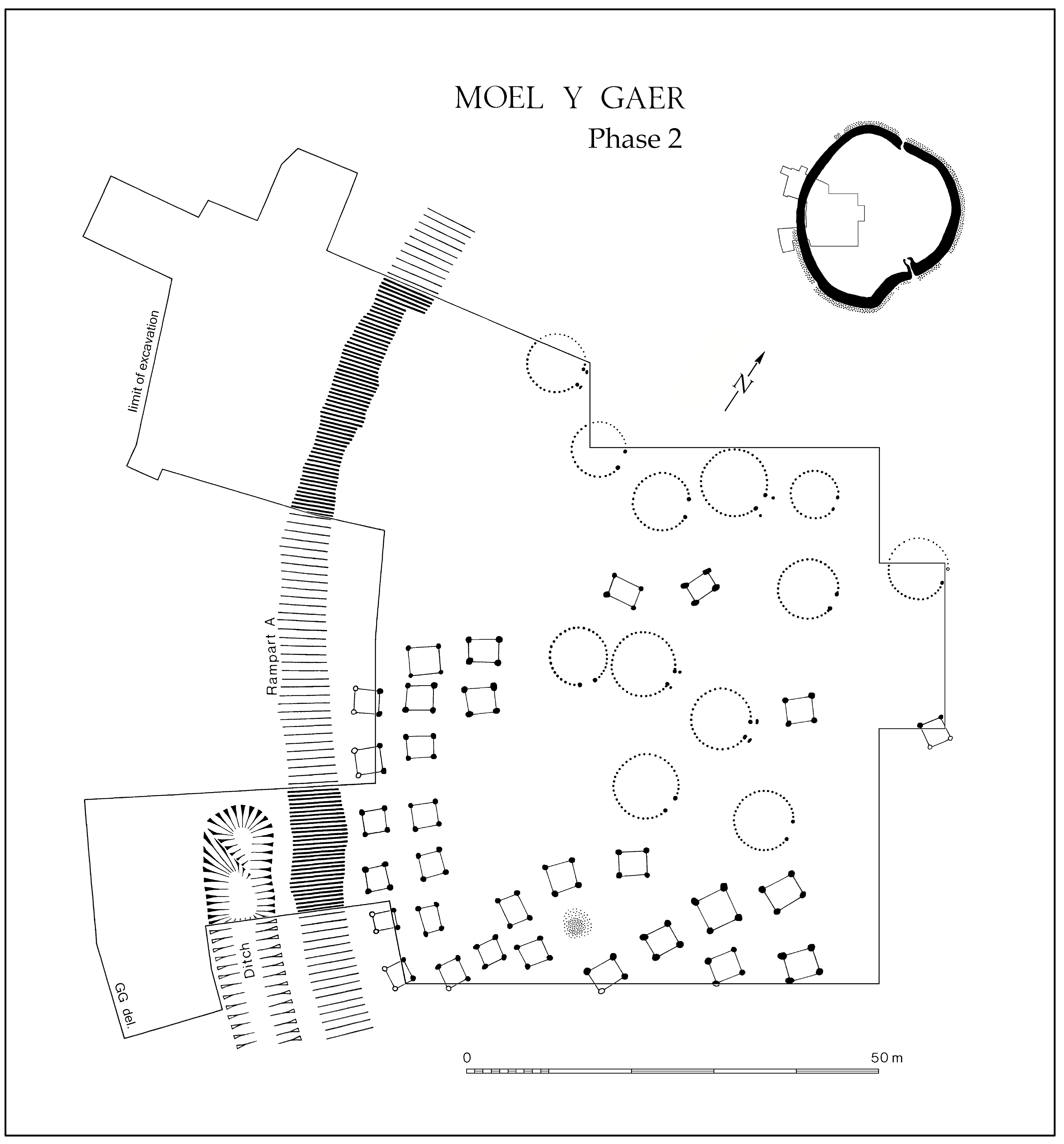
Figure E: Moel y Gaer, Rhosesmor: sketch-plan of Phase 2 structures identified by excavation, principally stake-wall roundhouses and four-posters, plus a large circular pit (stippled) possibly of this phase, with Rampart A (hatched) and a length of ditch (hachured). At top right, one-tenth-scale sketch shows the overall course of the related rampart (solid) and ditch (stippled), with the excavated area of 1972-4 outlined (but note that the number and form of entrances in this phase are actually uncertain)
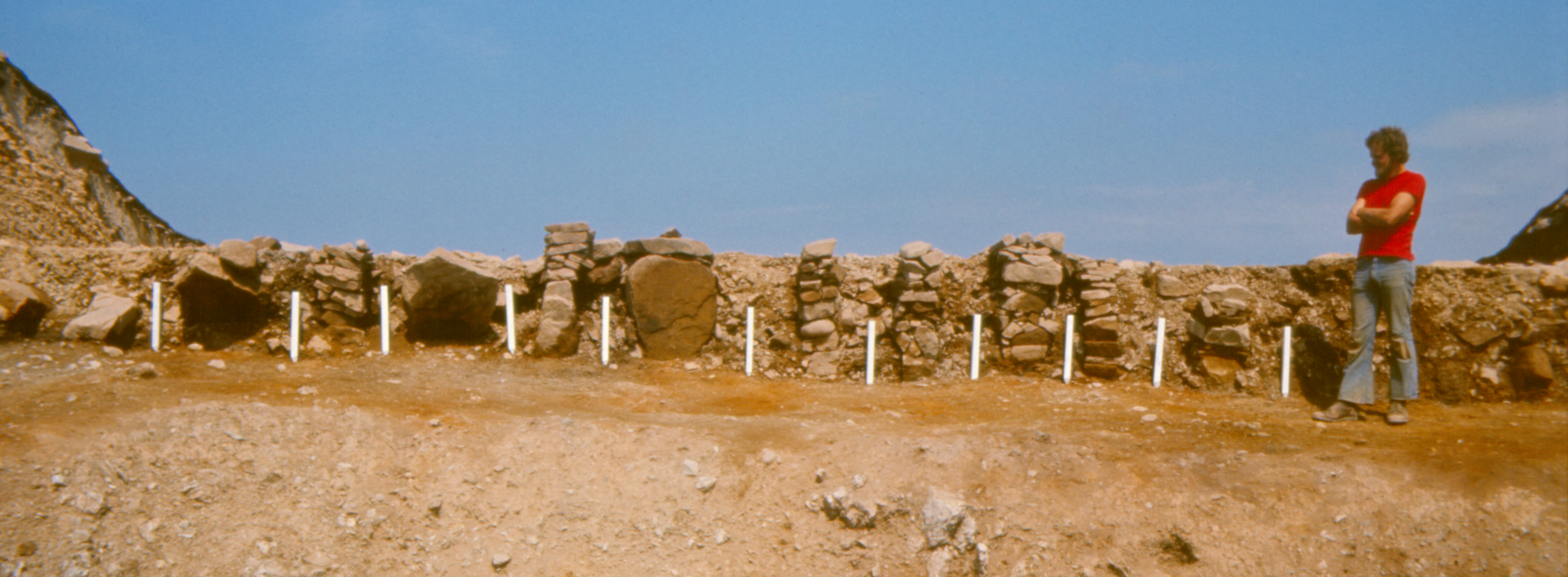
Figure F: Moel y Gaer, Rhosesmor: outer face of Rampart A of Phase 2, with orthostats and stacks of dry masonry infilling gaps between vertical timbers (their positions marked by white pegs, predicting where postholes would be found). Photograph G.C. Guilbert
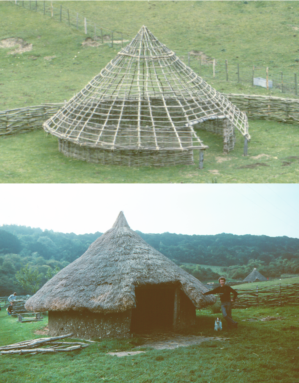
Figure G: Simulations of Moel y Gaer Phase 2 stake-wall roundhouses, based upon excavated ground-plans of one of the larger examples (above), c.7.7m in diameter (S33 in Guilbert 1977a, fig. 3), and the smallest (below), c.5.7m in diameter (B in Guilbert 1976a, fig. 5; S38 in Guilbert 1977a, fig. 3), as constructed by P.J. Reynolds at Butser Ancient Farm in 1983 and 1981 respectively. The upper view shows the wooden framework of wall, porch and roof, yet to be daubed and thatched, while the lower building is complete. Photographs P.D. Catherall and G.C. Guilbert
Figure H: Moel y Gaer, Rhosesmor: postholes of two of the Phase 2 four-posters, forming part of a gridded arrangement of such buildings. Photograph G.C. Guilbert
Figure I not used
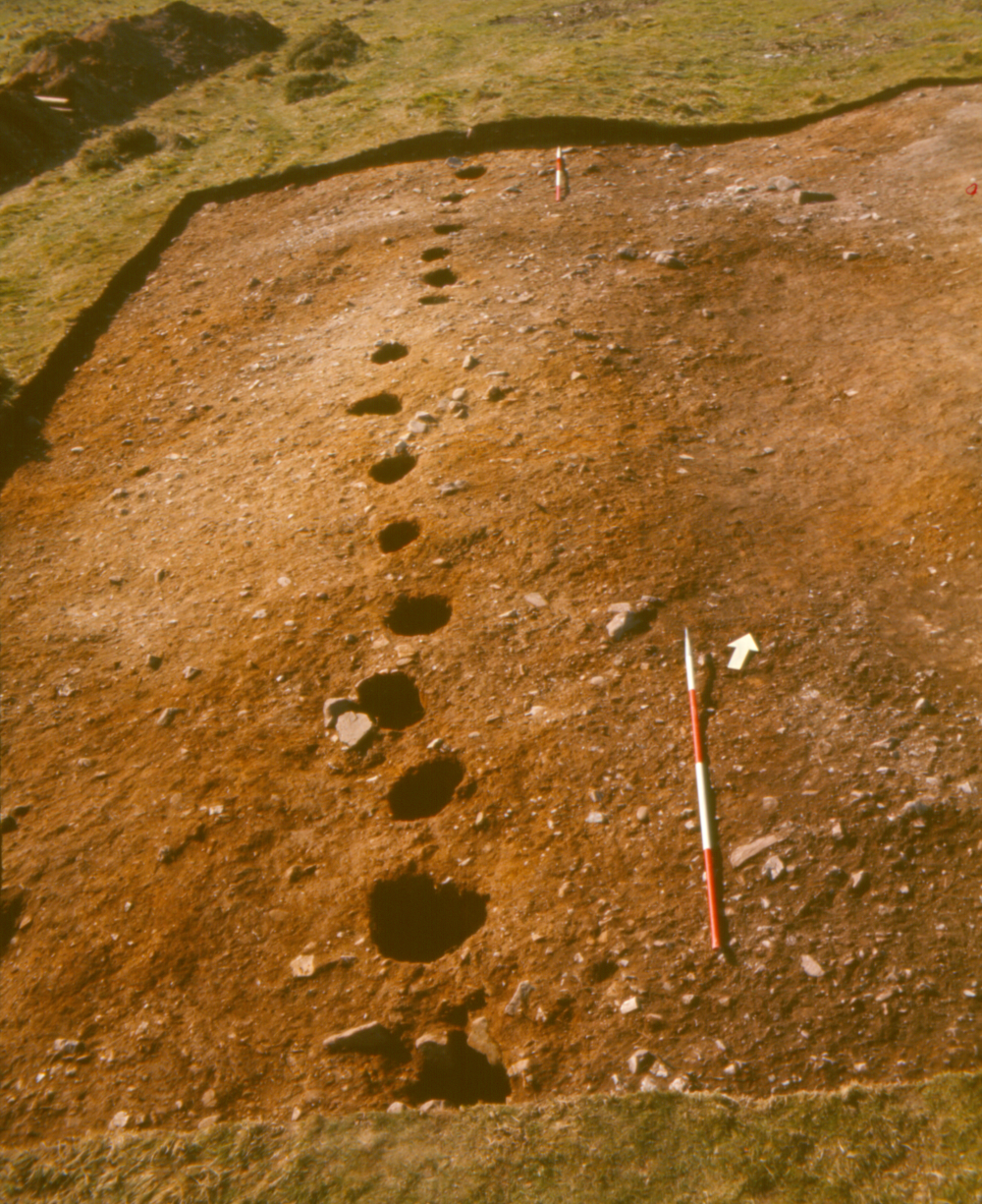
Figure J: Moel y Gaer, Rhosesmor: 12m length of the line of postholes of the outer 'palisade' (scales 2m long), with its low embankment and upslope quarry-scoop seen in profile beyond, probably representing an unfinished rampart of the final episode of hillfort-building. Photograph G.C. Guilbert.
Figure K: Moel y Gaer, Rhosesmor: excavation of a 15m length of inner bank in 1973, viewed from inside the hillfort, its development (i.e. Rampart B piled upon A) evident as distinct deposits in the lateral sections. In the foreground, two of a row of four-posters, which lay beneath the sloping tail of Rampart B, and, at left, part of the posthole-ring of an earlier roundhouse, which extended also under Rampart A. (A plan of this area of excavation is seen in Guilbert 1975a, fig. 3, with complementary photo in pl. XIIb, there looking along the line of the bank and down upon the crucial relationship of the successive ramparts to the underlying structures; see also Guilbert 1982, fig. 3.1 for spatial relationships between excavated structures of various phases.) Photograph G.C. Guilbert
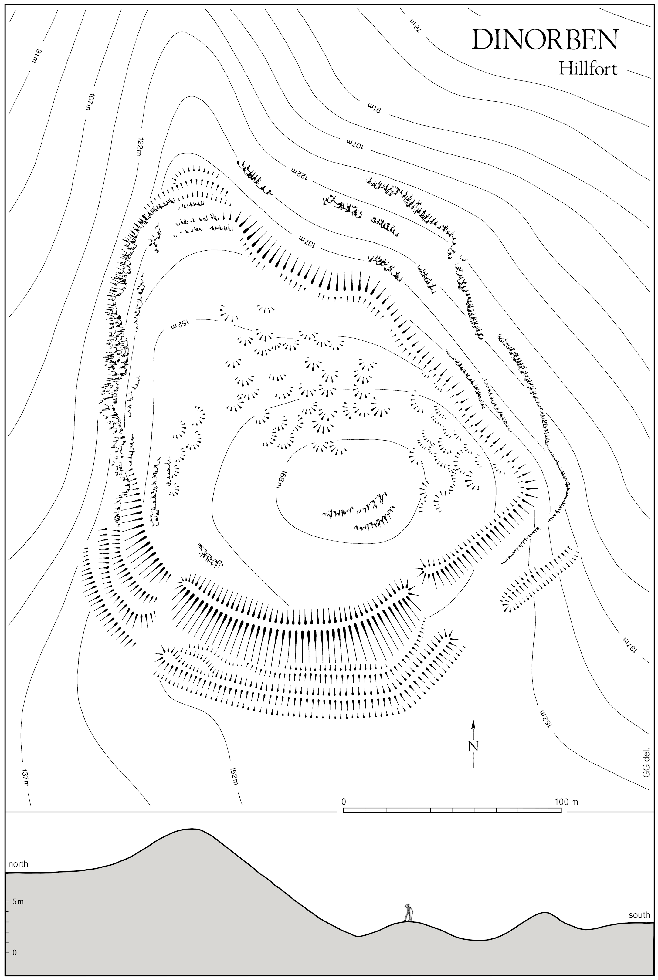
Figure L: Dinorben: plan of earthworks defining the promontory in combination with rock-outcrops along west and east, with internal platforms also hachured, and contour-lines at c.15m vertical interval (based upon Gardner and Savory 1964, figs 2 and 3, supplemented from other published sources, plus on-site amendment of south-east part in 1977). Across the foot, a profile crossing the central sector of the southern earthworks (at approximately five times the scale of the plan) shows the inner bank where it stood tallest (based upon Gardner and Savory 1964, fig. 7, section 1).
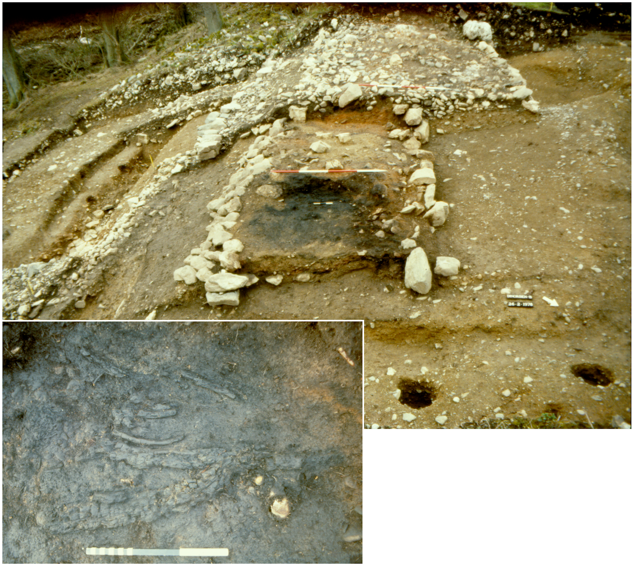
Figure M: Dinorben: 5.5m length of the early stone-revetted rampart, as uncovered in February 1978, with partially-excavated enlarged rampart in the background. The blackened area in the primary core (in front of scale with 50cm divisions) incorporated charred young branches and twigs used for radiocarbon-dating (inset photograph, with scale of 10cm and 1cm divisions). (Cf. Guilbert 1980, 337; and see Figure 7.) Photograph G.C. Guilbert.
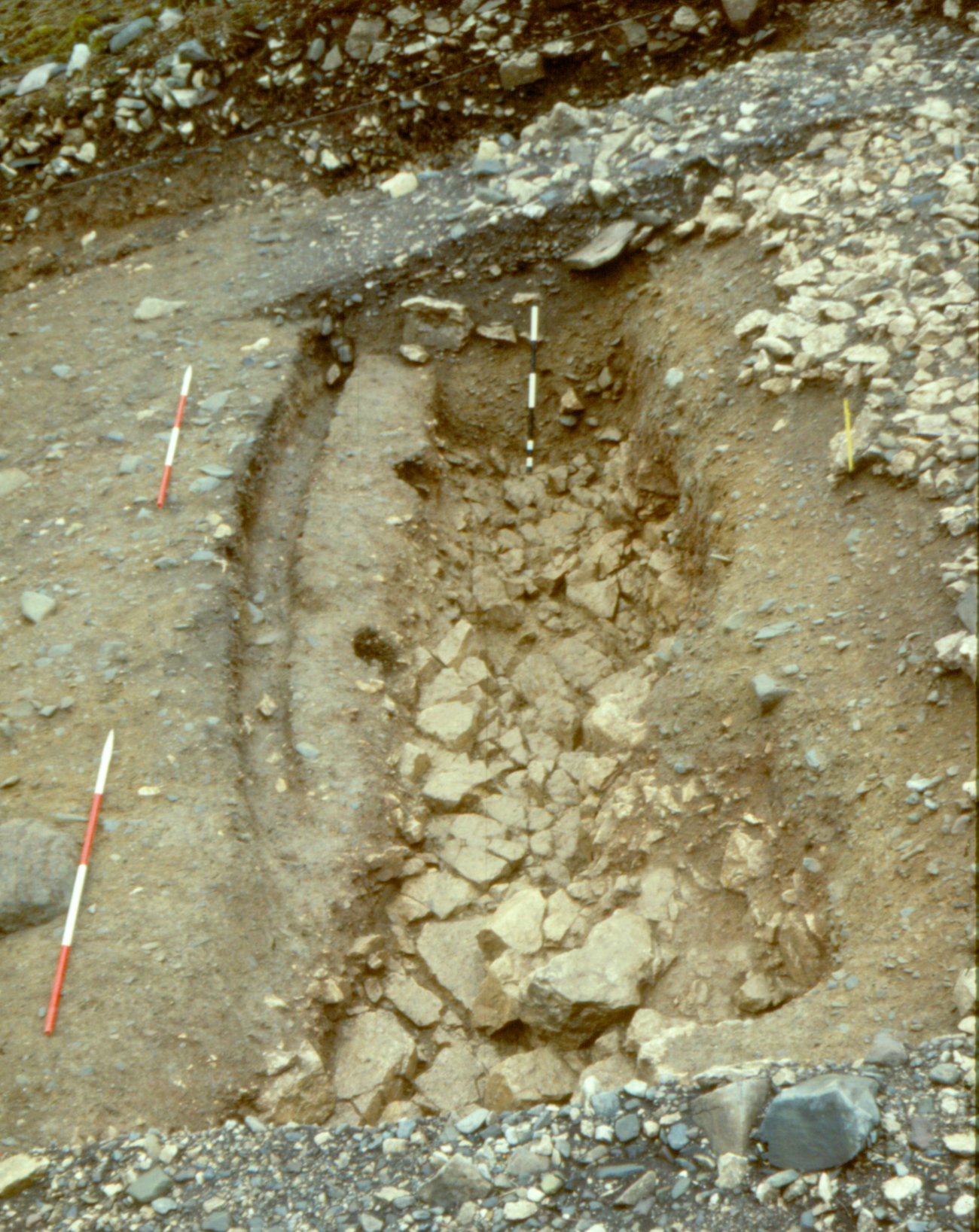
Figure N: Dinorben: 7.5m length of a ditch which antedated the earliest surviving build of rampart, with palisade-slot cut into ditch-counterscarp ('Ditch 1' and 'slot d' of Guilbert 1979a, 185 plan), during excavation in February 1978 (cf. Figure M, mid left). Vertical scale against section is 1m long overall; scales lying outside ditch have 50cm divisions. Photograph G.C. Guilbert.
Figure O not used
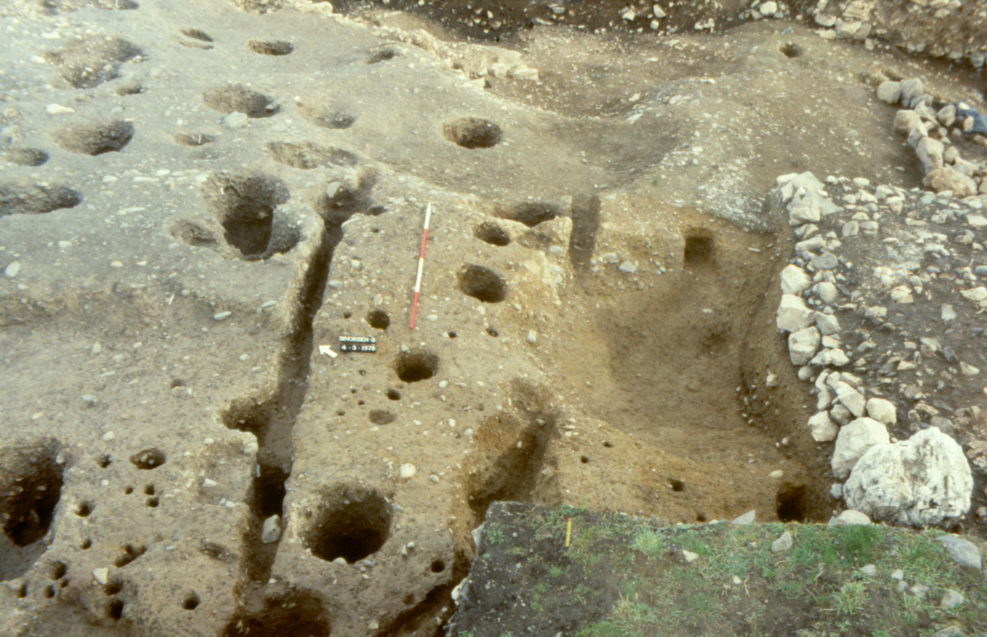
Figure P: Dinorben: remnants of two palisade-slots, partly removed by a building-platform and quarry-scoops behind the inner rampart, successive rear stone-revetments of which are seen to the right, during excavation in March 1978 (cf. Guilbert 1979a, 183 and 188 photos). Many of the postholes were cut from a higher level (cf. Figure R). Scale between slots has 50cm divisions. Photograph G.C. Guilbert.
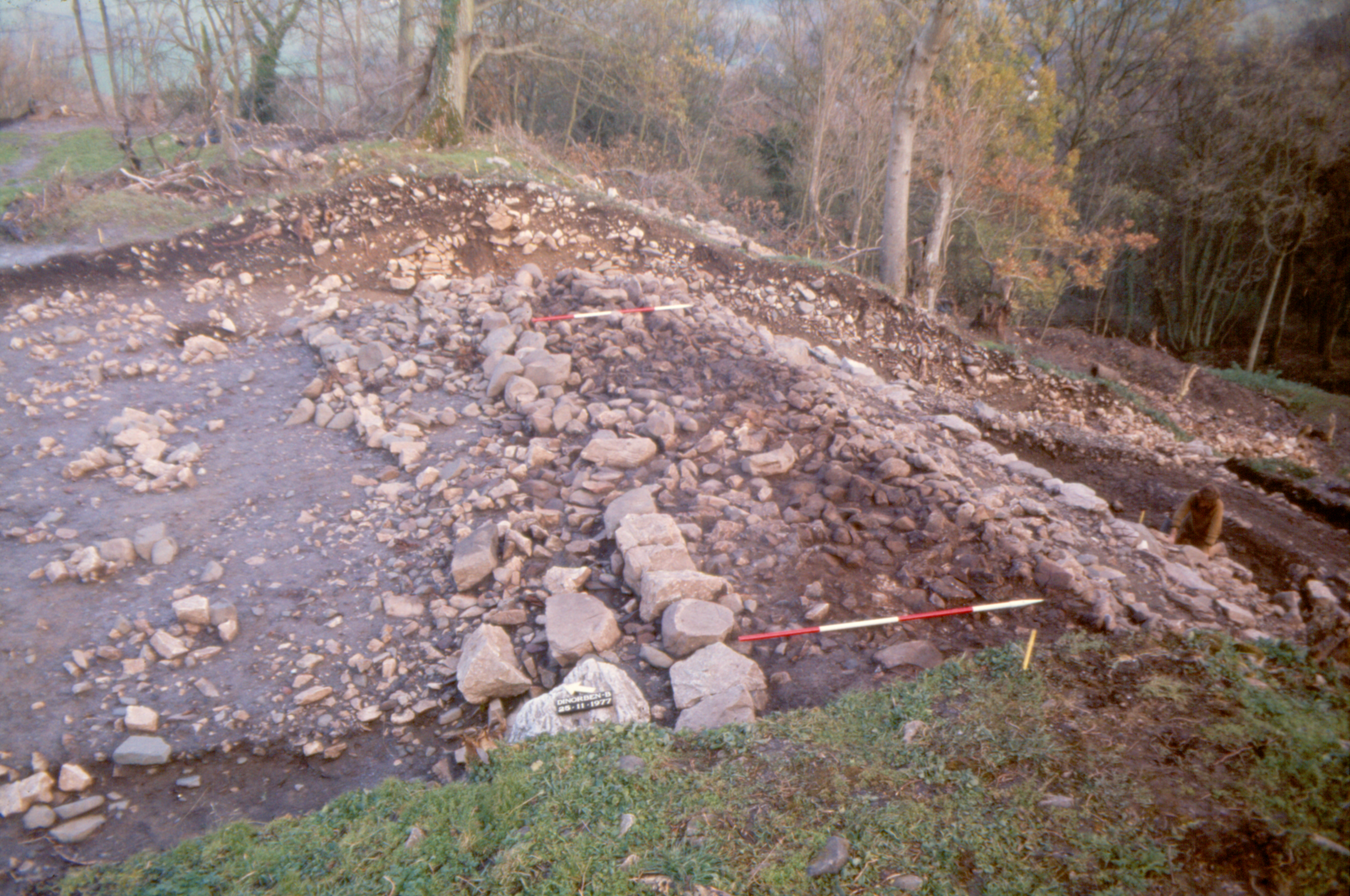
Figure Q: Dinorben: twin stone-revetments along the tiered inner side of the enlarged inner rampart, during excavation in November 1977; viewed from much the same spot as Figure P (cf. Guilbert 1979a, 184 middle photo). Scales have 50cm divisions. Photograph G.C. Guilbert.
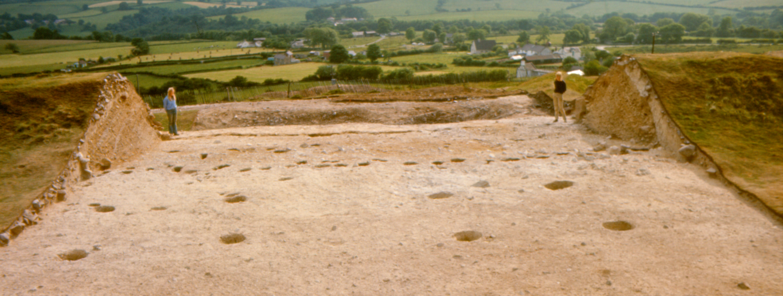
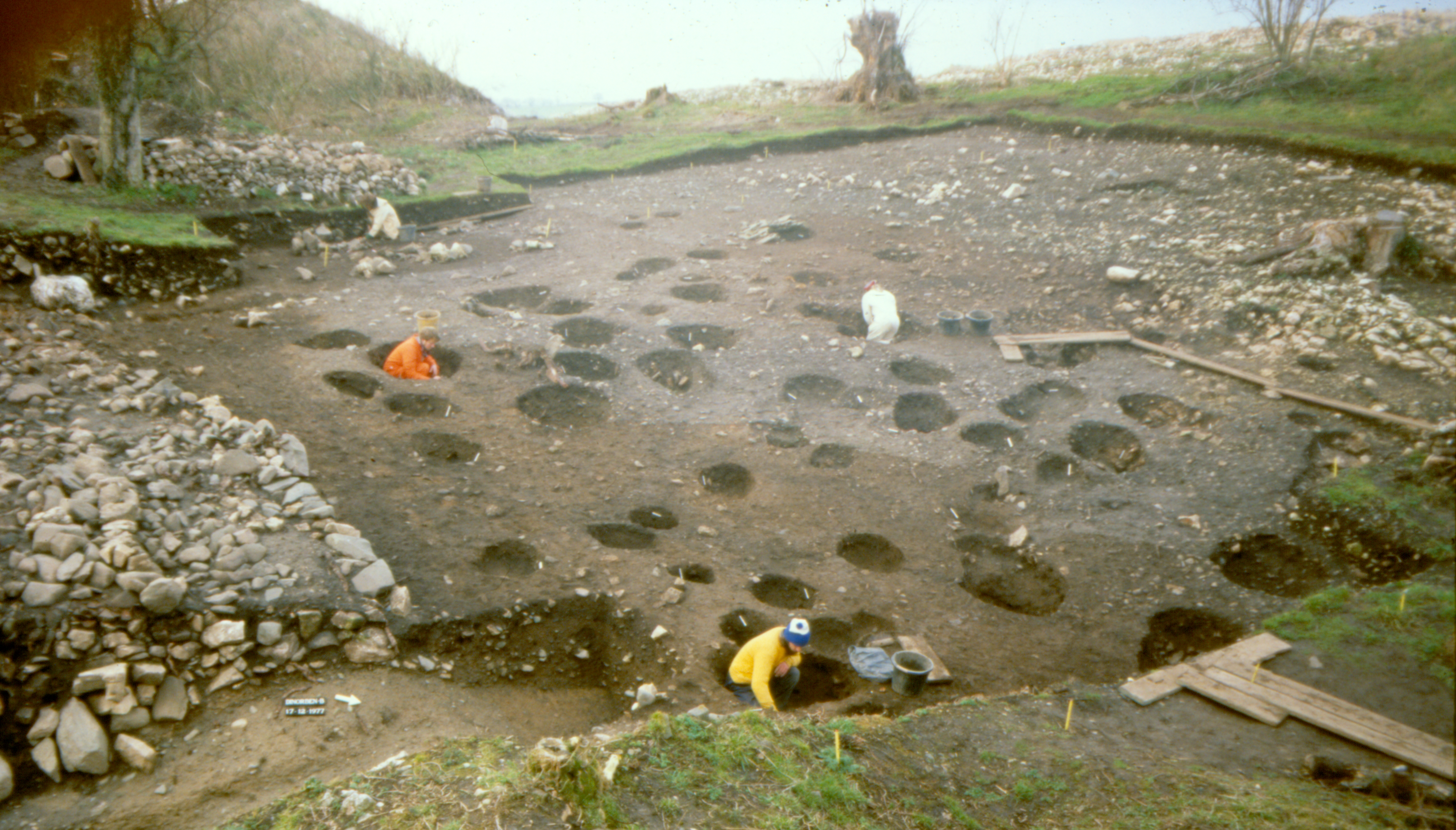
Figure R: Dinorben: palimpsest of postholes across c.400m² within the hillfort (almost 2% of its interior), including Romano-British four-post structures, under excavation in December 1977 (cf. Guilbert 1979a, 185 plan). The advancing quarry-face is situated directly beyond the large tree-stump in the background, with quarry-spoil piled at top left. Photograph G.C. Guilbert.
Internet Archaeology is an open access journal based in the Department of Archaeology, University of York. Except where otherwise noted, content from this work may be used under the terms of the Creative Commons Attribution 3.0 (CC BY) Unported licence, which permits unrestricted use, distribution, and reproduction in any medium, provided that attribution to the author(s), the title of the work, the Internet Archaeology journal and the relevant URL/DOI are given.
Terms and Conditions | Legal Statements | Privacy Policy | Cookies Policy | Citing Internet Archaeology
Internet Archaeology content is preserved for the long term with the Archaeology Data Service (ROR). Help sustain and support open access publication by donating to our Open Access Archaeology Fund.