The first stage in production was the creation of a structural mesh of the site, which would form a basis for all of the animated sequences. In recent years the combined use of low altitude aerial photography and SFM photogrammetry has emerged as a cost-efficient method for survey and modelling (Remondino et al. 2011). The flexibility and accuracy of these methods make them a highly viable tool for archaeological mapping and spatial analysis (Verhoeven et al. 2012). The mesh generated for 'Jarlshof' was not intended as a tool for survey or analysis but was required to provide an accurate framework on which photo-textures could be projected. A workflow was adopted to achieve this on a low budget, with limited access to low altitude aerial photography on site. This section of the article describes how these challenges were overcome using a combination of image-gathering hardware and image-processing software.
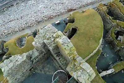
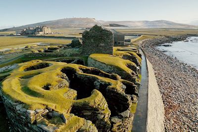
The sequences of photographs taken from the pole-mounted camera resulted in thousands of photographs positioned approximately 6m above the surface of the site (Figure 6). The pole-mounted camera was limited to areas that could be accessed on foot, making it impossible to traverse the site in a conventional grid pattern. Instead image sequences were taken along a series of paths that aimed to cover the entire surface of the site, including the sides of upstanding structures. The area adjacent to the sea wall, consisting of the broch, Iron Age wheelhouses and Laird's House, was particularly complex and restrictive to move around (Figure 7).
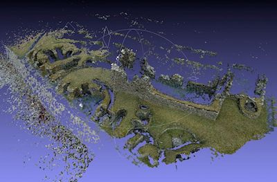
Due to the high number of photographs gathered and the unstructured nature of the camera positions, Microsoft Photosynth was used to derive the necessary point cloud data. While Autodesk 123D Catch was also considered (both solutions use cloud computing rather than processing locally), Photosynth was found to be more forgiving in that it was able to resolve images from erratic relative camera positions. Ideally, more structured photographs would be used in conjunction with software solutions that offered more overall control and flexibility. Agisoft Photoscan in particular has emerged as a valuable and versatile tool for site visualisation (see Verhoeven et al. 2012) and would be considered for future projects with similar demands. While point clouds derived from Photosynth are sparse compared with other solutions, the resulting mesh was of suitable density for the purpose of the animated outcome.
The site was divided into overlapping segments for SFM processing and the resulting point clouds meshed and combined using Meshlab, a tool developed with the support of the 3D-CoForm project. Point cloud data was imported into Meshlab using the function to download directly from Photosynth's online service. The Iterative Closest Point (ICP) alignment tool was used to re-align the overlapping segments. This tool required a meshed surface rather than a point cloud to calculate the best alignment, meaning that each segment had to be meshed before alignment. To avoid losing accuracy throughout an iterative meshing process, a meshing procedure was chosen that used original point cloud positions for the final vertex positions.
First the Photosynth point cloud data was imported and the normals calculated based upon the distribution of neighbouring points. Next the Poisson Surface Reconstruction algorithm was used to generate a mesh. This surface, which represented a smoothed average of the point positions, was then subdivided to create additional vertices before each vertex was snapped back to the nearest original point using the Vertex Attribute Transfer tool. This had the advantage that each vertex represents a position on the original point cloud. This meshing process was repeated once the segments were aligned, and as such it was important that the mesh remained true to the original point cloud at this stage to avoid a cumulative averaging out of the surface.
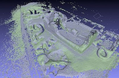
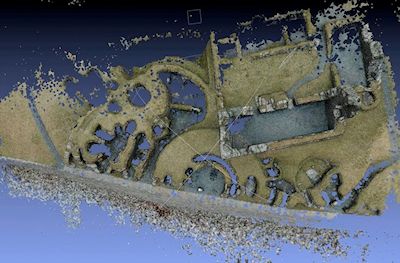
Once the overlapping segments were meshed they were aligned using Meshlab's ICP alignment tool. Control points on mutual areas of the surface were positioned manually to achieve a rough alignment and the algorithm was then used to relax the segments into their positions of best fit. The example here shows the alignment of two segments covering an area accessible from the sea wall (Figs 8 to 10). The two segments were derived from sequences of photographs taken from opposing directions. While each segment contains 'shadows' where there are no data behind upstanding structures, the coverage is much improved when the two are combined. It was found that sequences of photographs from opposing directions like these could rarely be combined at the point cloud stage within Photosynth. This was possibly because the grass and dry-stone surfaces changed appearance dramatically depending on the viewing angle, which had the effect of reducing the number of relatable points.
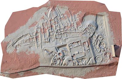
Once the meshing process had been repeated for an initial ten segments there remained gaps that could not be resolved from the existing photographs. These areas included the corners of the Historic Scotland property-in-care area, along with some of the more occluded areas within the upstanding structures. Photographs for these areas were gathered during a second phase of fieldwork. To guide this second phase a plan of the site was made with areas below a certain threshold of density highlighted in red (Figure 11). The same pole-mounted camera method was then used to target the problem areas with a further eleven segments.
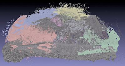
Once processed, these segments were added to the existing mesh and aligned using the ICP alignment tool (Figure 12). To create a single meshed surface the aligned segments were combined into one mesh and the first stages of the meshing process repeated to create a single unified surface. The resulting master mesh was then further subdivided for a smoother end result, and finally cut into seven sections to aid the texturing and rendering process.